Surface plate structure for bottom of microwave oven chamber

A microwave oven and oven cavity technology, applied in the field of microwave ovens, can solve the problems of increasing user dissatisfaction, unable to cook food, unable to heat food evenly, etc., and achieve the effects of increasing the purchase rate and shortening the cooking time.

Inactive Publication Date: 2006-03-29
LG ELECTRONICS (TIANJIN) APPLIANCES CO LTD
View PDF0 Cites 9 Cited by
  • Summary
  • Abstract
  • Description
  • Claims
  • Application Information

AI Technical Summary

Problems solved by technology

In this case, the microwave irradiating the inside of the oven cavity will not irradiate the food until it hits the wall, so there will be a disadvantage of not directly heating the food inside the oven cavity.
[0023] In addition, the microwave that irradiates the food does not directly irradiate the food, so there are disadvantages that the food cannot be heated evenly and the cooking time of the food is long.
[0024] In addition, if the cooking time becomes longer, the efficiency of the microwave oven will decrease, and the food cannot be cooked within the desired time, so there is a disadvantage of increasing user dissatisfaction.

Method used


Image

  • Surface plate structure for bottom of microwave oven chamber
  • Surface plate structure for bottom of microwave oven chamber
  • Surface plate structure for bottom of microwave oven chamber

Examples


Embodiment Construction

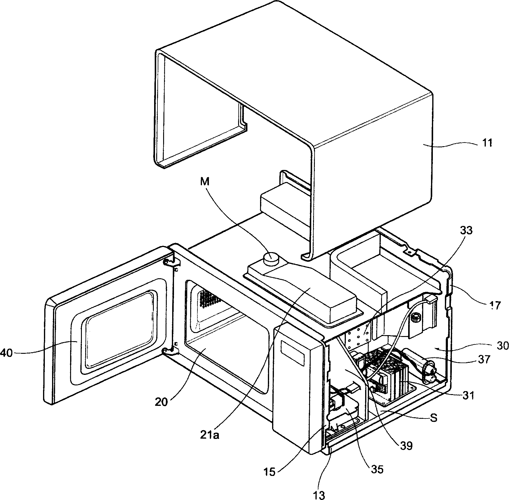
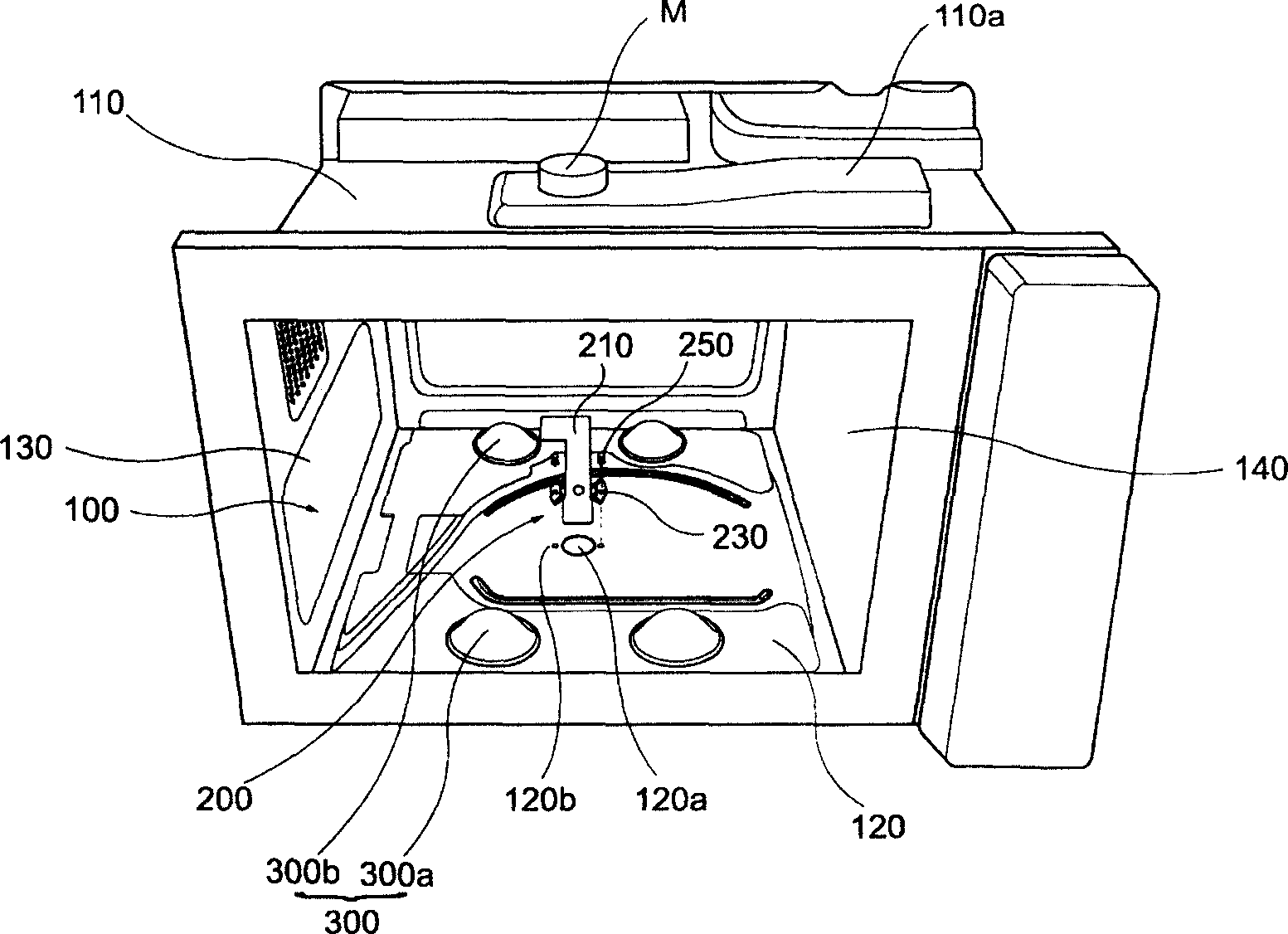
[0044] Below in conjunction with accompanying drawing and specific embodiment the present invention is described in further detail: image 3 It is an oblique view of the oven cavity of a preferred embodiment of the lower panel structure of the microwave oven cavity of the present invention. As shown in the figure, the oven chamber 100 is roughly shaped like a rectangular box, and has a predetermined space inside for placing food. The oven cavity 100 includes an upper panel 110 disposed above, a lower panel 120 disposed below, a left side panel 130 disposed on the left side, and a right side panel 130 disposed on the right side. Furthermore, the furnace cavity 100 is formed by combining the above panels 110, 120, 130, 140 with each other.

[0045] The above-mentioned upper panel 110 forms the upper surface of the furnace chamber 100, and the waveguide 110a is provided on the outer surface thereof. The waveguide 110a plays a role of guiding the microwave generated by the magne...


PUM


Abstract

The present invention discloses an oven cavity lower portion panel structure of microwave oven, It includes oven cavity for placing cooking material, lower portion panel set in the lower portion of oven cavity and formed into the appearance of lower surface of oven cavity and stirring fan which is fixed on the upper surface of lower portion panel and used for dispersing microwave irradiating oven cavity, on the lower portion panel of oven cavity a forming portion is set, and said stirring fan can utilize the forming portion to reflect microwave towards several directions.

Description

technical field [0001] The invention relates to a microwave oven, in particular to a lower panel structure of a microwave oven cavity. More specifically, it relates to a lower panel structure of a microwave oven cavity formed with several molded parts. Background technique [0002] In general, a microwave oven is a device that generates microwaves from a magnetron in response to power-on, and irradiates the microwaves to a heated object such as food to cook food. Such microwave ovens are classified into domestic microwave ovens equipped with small magnetrons and commercial microwave ovens equipped with large or multiple magnetrons. [0003] In addition, microwave ovens can also be distinguished according to the method of heating food, household microwave ovens use a glass turntable method that rotates food, and commercial microwave ovens mainly use a stirring fan method that disperses microwaves. [0004] In addition, commercial microwave ovens are mainly used in convenien...

Claims


Application Information

Patent Timeline
Patent Type & Authority Applications(China)
IPC IPC(8): F24C7/02F24C15/00
Inventor 李尚律
Owner LG ELECTRONICS (TIANJIN) APPLIANCES CO LTD
Why Eureka
Try Eureka