Oil distributing device for air conditioner

An oil separator and air conditioner technology, which is applied in the field of air conditioner oil separators, can solve the problems of too many lubricating oils, complex structures, and insufficient separation of lubricating oils, so as to improve the oil separation efficiency, simplify the production process, and reduce the production cost. effect of cost

Inactive Publication Date: 2006-03-29
LG ELECTRONICS (TIANJIN) APPLIANCES CO LTD
View PDF0 Cites 6 Cited by
  • Summary
  • Abstract
  • Description
  • Claims
  • Application Information

AI Technical Summary

Problems solved by technology

Although the outdoor unit 1 of the air conditioner has an oil separator 12, the inside of the oil separator 12 has a mesh screen 12b or a metal filler, and is also provided with an upper plate 12c and a lower plate 12d etc. to filter lubricating oil, but Relative to the oil separation efficiency, the structure is too complicated
[0029] In addition, when the variable-speed compressor 10" is running at high frequency, the flow rate of the cold coal discharged from the variable-speed compressor is particularly high, so it is possible that the passing cold coal cannot be fully filtered
[0030] When the flow rate of the cold coal is too fast, the lubricating oil cannot be separated sufficiently, resulting in too much lubricating oil in the cold coal, which affects the heat exchange efficiency and reduces the performance of the entire air conditioner

Method used


Image

  • Oil distributing device for air conditioner
  • Oil distributing device for air conditioner
  • Oil distributing device for air conditioner

Examples


Embodiment Construction

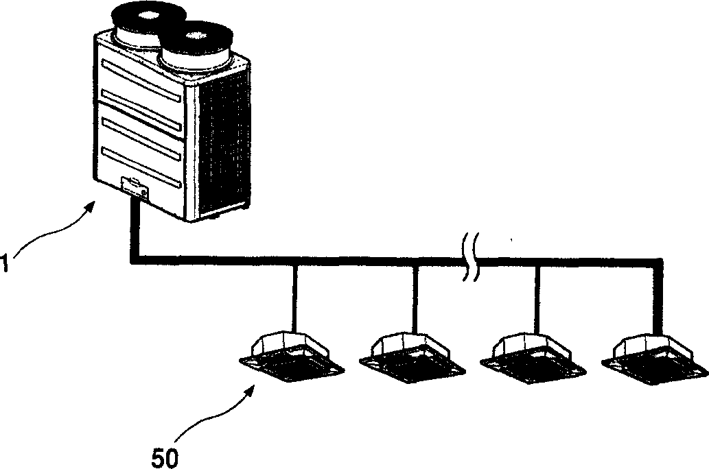
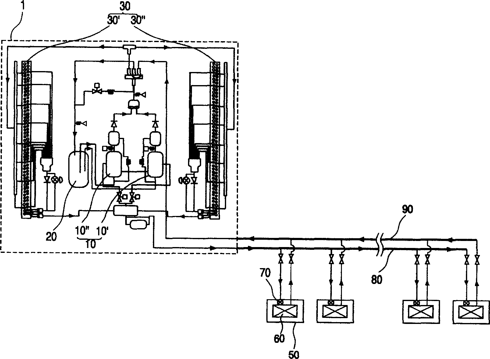
[0089] The present invention is described in further detail below in conjunction with the accompanying drawings and specific embodiments: Figure 7 It is a schematic diagram of the setting state of the air conditioner of the present invention. Figure 8 It is a block diagram of the structure of the central air conditioner and the flow state of the refrigerant in the present invention. As shown in the figure, the outdoor unit 100 consists of a fixed-speed compressor 120, a variable-speed compressor 120', a liquid storage tank 132, an outdoor heat exchanger 180, and an outdoor solenoid valve 102 (LEV: linear expansion valve, hereinafter referred to as outdoor LEV), etc. composition. The indoor unit 200 is composed of an indoor heat exchanger 202, an expansion valve 204, and the like.

[0090] In a central air conditioner, a plurality of indoor units 200 are connected to one or more than two outdoor units 100 . A common liquid pipe 210 as a single pipe and a common air pipe 21...


PUM


Abstract

The present invention discloses an oil separator of air conditioner. It includes external shell which is used for forming appearance, refrigerant discharge tube which is extended into the interior of external shell, one side of said refrigerant discharge tube is equipped with an oil-separating fan, the oil-separating fan is set in the interior of external shell, and can be rotated to produce vortex flow, the refrigerant in the external shell interior can be passed through the refrigerant discharge tube and discharged, the side face of the external shell is equipped with refrigerant supply tube, said refrigerant supply tube can supply refrigerant to the interior of the external shell, the oil-separating fan can be rotated by utilizing refrigerant discharged from refrigerant supply tube so as to separate the lubricating oil from refrigerant.

Description

technical field [0001] The invention relates to an air conditioner, in particular to an air conditioner oil separator. That is, the lubricating oil is recovered by utilizing the centrifugal force generated by the rotation of the oil separation fan. Background technique [0002] An air conditioner is a device that inhales hot air in the room, exchanges heat with it with a low-temperature refrigerant, and discharges the heat-exchanged air to the room. The air conditioner cools the room by repeating the process, or heats the air in the room by performing the reverse operation of the above process. The air conditioner is composed of compressor-condenser-expansion valve-evaporator, forming a loop. [0003] Recently, air conditioners having various additional functions such as an air filtering function and a dehumidification function have also appeared on the market. This air conditioner can take in indoor air from the outside, filter it, and discharge clean air. It can also d...

Claims


Application Information

Patent Timeline
IPC IPC(8): F25B43/02
Inventor 金秉淳
Owner LG ELECTRONICS (TIANJIN) APPLIANCES CO LTD
Why Eureka
Try Eureka