Optical fiber end surface grinding device

An end face and tooling technology, used in grinding devices, grinding machine tools, optics, etc., can solve problems such as non-parallel, inconvenient automation, and complexity.

Inactive Publication Date: 2006-03-29
凌国基
View PDF4 Cites 7 Cited by
  • Summary
  • Abstract
  • Description
  • Claims
  • Application Information

AI Technical Summary

Problems solved by technology

As a result, a torsion force is generated, which makes the set tilt, resulting in uneven pressure
[0018] 2. If the optical fiber end face holder is clamped and fixed, the unevenness of the grinding surface and the holder will also cause uneven pressure
But this is not a natural contact, there will always be a little bit of non-parallel
In addition, with this design, the pressure between the end face of the optical fiber 43 and the grinding surface 45 is exerted from the bottom to the top. This method is too complicated, and it is not convenient for automation.
In addition, if the design of the grinding surface is long as shown in Figure 3, and there are several optical fiber end face holders, and at the same time slide on this long grinding surface, it is necessary to keep the different positions of each holder. It is even more difficult if the pressure on the fiber end face is uniform

Method used


Image

  • Optical fiber end surface grinding device
  • Optical fiber end surface grinding device
  • Optical fiber end surface grinding device

Examples


Embodiment Construction

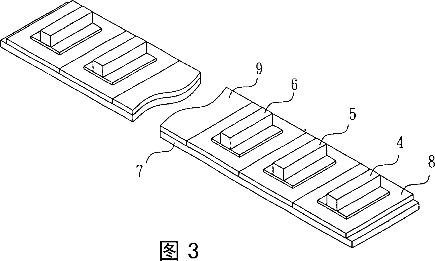
[0073] see Figure 7 , Figure 8 , Figure 9 , Figure 10 shown. The holders 50 and 50' of the first embodiment of the present invention respectively include a fixing groove 51 recessed below the body at the center of the body to accommodate a fixing rod 52; the sides of the body near the periphery have plural symmetry The accommodating grooves 53, 53', 53" are for accommodating the weight 54. The accommodating grooves 53, 53', 53" are respectively arc groove-shaped, round-shaped and long groove-shaped. The bodies of the holders 50, 50' are respectively circular and square. The body of the fixture 50 is combined with a plurality of clamps 500 . Each clamp 500 engages at least one fiber end face ferrule 55 to engage an optical fiber 56 to be polished. There is a grinding surface 57 below the ferrule 55 , and the grinding surface 57 is combined on the base 58 . The upper end of the fixing rod 52 is combined with a bracket 59 . The bottom of the fixing rod 52 has a socket...


PUM


Abstract

The present invention relates to an optical-fibre end face grinding equipment for combining optical-fibre to be ground. It includes a self-body with fixed groove. Said fixed groove can be used for containing a fixed rod, a supporting frame is combined on the upper end of said fixed rod. Said self-body is combined with several clamps, every clamp is combined with a collar. Besides, said invention also provides the concrete structure of said fixed rod, and provides the application method of said grinding equipment to raise grinding speed and quality.

Description

technical field [0001] The invention relates to a device for grinding the end face of a workpiece, in particular to a device for arranging the end face of an optical fiber to be ground. Background technique [0002] Optical fiber communication is an indispensable tool for current and future communication technology. Just like the communication components of a wired communication system, signal lines and signal connectors are required to be connected together. Fiber optic communication systems also require fiber optic connectors. The optical fiber connector is mainly made by passing the optical fiber through a ferrule with a hole in the middle, and then sticking it with an adhesive. This ferrule can be made of plastic, glass or ceramics. Place the end face of the optical fiber with the ferrule on the elastic grinding surface and pressurize it, and then rough grind, fine grind, and polish to form a convex spherical surface. This convex sphere must be a mirror without blemis...

Claims


Application Information

Patent Timeline
Patent Type & Authority Applications(China)
IPC IPC(8): G02B6/00B24B37/00B24B37/10
Inventor 凌国基
Owner 凌国基
Why Eureka
Try Eureka