Lubricating oil reaction kettle

A technology of reaction kettle and lubricating oil, which is applied in the directions of lubricating composition, petroleum industry, treatment of hydrocarbon oil, etc., can solve the problems of increased pressure of the reaction kettle and cannot be effectively controlled, and achieves accurate pressure control, easy calculation and control, cost saving effect

Inactive Publication Date: 2016-11-23
四川省德阳昌盛至轩石油化工厂
View PDF1 Cites 2 Cited by
  • Summary
  • Abstract
  • Description
  • Claims
  • Application Information

AI Technical Summary

Problems solved by technology

[0004] The above-mentioned prior art cannot follow the addition of hydrogen, and the pressure of the reactor will gradually increase, which cannot be effectively controlled

Method used


Image

  • Lubricating oil reaction kettle

Examples


Embodiment 1

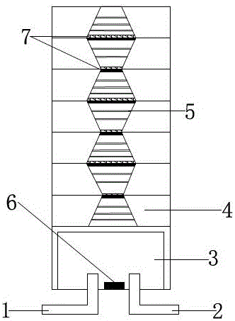
[0026] A lubricating oil reactor, including a reactor, an oil inlet pipe 1 and a hydrogen inlet pipe 2, is characterized in that: the reactor includes a reaction tank 3 and a plurality of unit units 4, and a plurality of unit units 4 overlap above the reaction tank 3, Both the oil inlet pipe 1 and the hydrogen inlet pipe 2 lead into the bottom of the reaction tank 3; the oil inlet pipe 1 and the hydrogen inlet pipe 2 are higher than the bottom of the reaction tank 3; each unit 4 is provided with a plurality of movable baffles 5 The unit element 4 is hollow; the upper end of the unit element 4 located on the uppermost layer is sealed; the inner side of the bottom of the reaction tank 3 is connected with a pressure sensor.

Embodiment 2

[0028] A lubricating oil reactor, including a reactor, an oil inlet pipe 1 and a hydrogen inlet pipe 2, is characterized in that: the reactor includes a reaction tank 3 and a plurality of unit units 4, and a plurality of unit units 4 overlap above the reaction tank 3, Both the oil inlet pipe 1 and the hydrogen inlet pipe 2 lead into the bottom of the reaction tank 3; the oil inlet pipe 1 and the hydrogen inlet pipe 2 are higher than the bottom of the reaction tank 3; each unit 4 is provided with a plurality of movable baffles 5 The unit element 4 is hollow; the upper end of the unit element 4 located on the uppermost layer is sealed; the inner side of the bottom of the reaction tank 3 is connected with a pressure sensor.

[0029] The hollow part of the unit element 4 is in the shape of a truncated cone, and the ends of the truncated cone are connected in sequence.

Embodiment 3

[0031] A lubricating oil reactor, including a reactor, an oil inlet pipe 1 and a hydrogen inlet pipe 2, is characterized in that: the reactor includes a reaction tank 3 and a plurality of unit units 4, and a plurality of unit units 4 overlap above the reaction tank 3, Both the oil inlet pipe 1 and the hydrogen inlet pipe 2 lead into the bottom of the reaction tank 3; the oil inlet pipe 1 and the hydrogen inlet pipe 2 are higher than the bottom of the reaction tank 3; each unit 4 is provided with a plurality of movable baffles 5 The unit element 4 is hollow; the upper end of the unit element 4 located on the uppermost layer is sealed; the inner side of the bottom of the reaction tank 3 is connected with a pressure sensor.

[0032] The hollow part of the unit element 4 is in the shape of a truncated cone, and the ends of the truncated cone are connected in sequence.

[0033] Both the upper end and the lower end of the unit element 4 are connected with sealing rings 6 .


PUM


Abstract

The invention discloses a lubricating oil reaction kettle which comprises a reaction kettle, an oil inlet pipe and a hydrogen inlet pipe, wherein the reaction kettle comprises a reaction tank and multiple single elements; the multiple single elements are overlapped above the reaction tank; both the oil inlet pipe and the hydrogen inlet pipe lead into the reaction tank from the bottom of the reaction tank; multiple movable baffle plates are arranged in each single element; the single elements are hollow; a pressure sensor is connected to the inner side of the bottom of the reaction tank. Both the oil inlet pipe and the hydrogen inlet pipe lead into the reaction tank from the bottom of the reaction tank, and both the added oil inlet pipe and hydrogen inlet pipe are distributed upwards from the bottom. The pressure sensor arranged on the inner side of the bottom of the reaction kettle is adopted for monitoring, the movable baffle plate of the bottommost layer is opened when pressure is excessively high, the movable baffle plate of the second bottommost layer is opened if the pressure is still high, and so on. The movable baffle plates are opened or closed to regulate the pressure in the reaction kettle, so that the aim of controlling the pressure of a reaction system is fulfilled.

Description

technical field [0001] The invention belongs to the field of reactors, in particular to lubricating oil reactors. Background technique [0002] At present, due to the increasing use of mechanical equipment in people's lives, the demand for lubricating oil as a liquid lubricant to protect machinery and processed parts is also increasing, so there are more and more businesses producing lubricating oil. However, lubricating oil needs to be refined in the production process to improve the quality of lubricating oil. Lubricating oil refining includes two types of clay refining and hydrofining. The clay refining process is cumbersome and consumes a lot of time, and has been slowly produced by lubricating oil. Discarded by merchants, the oil after hydrofining has improved color, stability and odor, and the susceptibility to antioxidants has been significantly improved. The content of hydrocarbon elements such as sulfur, nitrogen and oxygen is reduced, and the yield is higher than ...

Claims


Application Information

Patent Timeline
IPC IPC(8): B01J8/00B01J8/02C10M177/00C10G45/02
CPCB01J8/001B01J8/02B01J2208/00539C10G45/02C10G2300/1062C10G2400/10C10M177/00
Inventor 周昌国
Owner 四川省德阳昌盛至轩石油化工厂
Why Eureka
Try Eureka