Roller chain with greater link joint height

A roller chain, high-level technology, applied in the direction of transmission chain, etc., can solve space problems, limited clearance and other problems

Active Publication Date: 2006-04-05
JOH WINKLHOFER & SOHNE
View PDF5 Cites 3 Cited by
  • Summary
  • Abstract
  • Description
  • Claims
  • Application Information

AI Technical Summary

Problems solved by technology

In some applications, such as when roller chains are used as timing chains on internal combustion engines, significant space problems occur to the extent that clearances using most standard chains are very limited

Method used


Image

  • Roller chain with greater link joint height
  • Roller chain with greater link joint height

Examples


Embodiment Construction

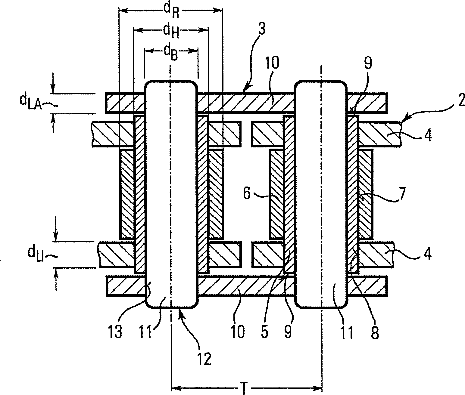
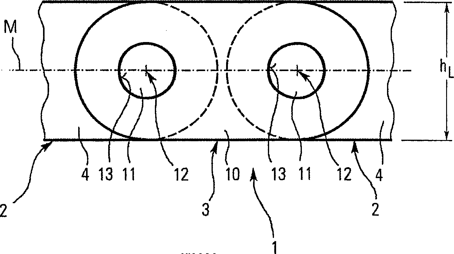
[0021] figure 1 The roller chain shown in consists of alternating inner 2 and outer 3 links.

[0022] Each inner chain link 2 includes: two parallel inner chain plates 4 spaced apart from each other, two parallel connecting sleeves 5 arranged spaced apart from each other and connecting the inner chain plates 4 to each other, and two rollers 6 , in each case one of which is supported for rotation on the outer surface 7 of the connecting sleeve 5 . The connecting sleeve 5 is pressed into the opening 8 of the inner link plate 4 , wherein the face sides 9 of the connecting sleeve 5 protrude slightly beyond the inner link plate 4 . The length of the rollers 6 is slightly shorter than the internal distance between the two inner chain plates 4 .

[0023] Each outer chain link 3 includes two outer chain plates 10 arranged at a parallel distance to each other and two connecting pins 11 arranged at a parallel distance to each other. Each connecting pin 11 passes in each case through ...


PUM


Abstract

A roller chain of a metallic material, with alternating inner and outer chain links which are respectively joined together via a chain joint, whereby the outer chain links comprise two parallel outer plates, joined together by means of two parallel joint pins, and the inner chain links comprise two parallel inner plates, joined together by means of two parallel joint sleeves, a joint pin of an outer chain link extends in each case through a joint sleeve of an inner chain link to form a chain joint and a rotatable roller is arranged on the outer surface of the joint sleeve, whereby a size ratio of the height of the outer and inner plates to the external diameter of the roller is greater than 1.4, and a size ratio of the mean thickness of the inner plate to the mean thickness of the outer plate is greater than 1.1.

Description

technical field [0001] The invention relates to a roller chain of metallic material, having inner and outer links alternating with each other and in each case connected to each other by links, wherein the outer links consist of two parallel outer chain plates, composed of two Two parallel connecting pins are connected together, while the inner link consists of two parallel inner link plates connected together by two parallel connecting sleeves, the connecting pins of the outer links pass through the inner links in each case The connecting sleeve is used to form a link, and a rotatable roller is arranged on the outer surface of the connecting sleeve. [0002] Examples of roller chains can be found in US 5382199A, GB 2398852A, EP 0257661A and US 5799479A. Background technique [0003] This type of roller chain is used very frequently, especially in applications where good acoustic properties of the chain are required. The rollers configured for rotation on the coupling bushi...

Claims


Application Information

Patent Timeline
Patent Type & Authority Applications(China)
IPC IPC(8): F16G13/02
Inventor T·芬克M·帕纳斯M·奥尔哈默H·弗兰克S·贝尔梅
Owner JOH WINKLHOFER & SOHNE
Why Eureka
Try Eureka