Signal light system of automatic regulating according to traffic flow

A technology of automatic regulation and traffic flow, applied in the traffic control system of road vehicles, traffic control systems, instruments, etc., can solve problems such as waste of time, waste of road resources, unreasonable allocation, etc., and achieve full use of road resources and reasonable allocation Effect

Inactive Publication Date: 2006-04-12
朱汪逸
View PDF0 Cites 8 Cited by
  • Summary
  • Abstract
  • Description
  • Claims
  • Application Information

AI Technical Summary

Problems solved by technology

In the current system, the switching time is fixed. When the number of vehicles on the road va

Method used


Image

  • Signal light system of automatic regulating according to traffic flow
  • Signal light system of automatic regulating according to traffic flow
  • Signal light system of automatic regulating according to traffic flow

Examples


Embodiment Construction

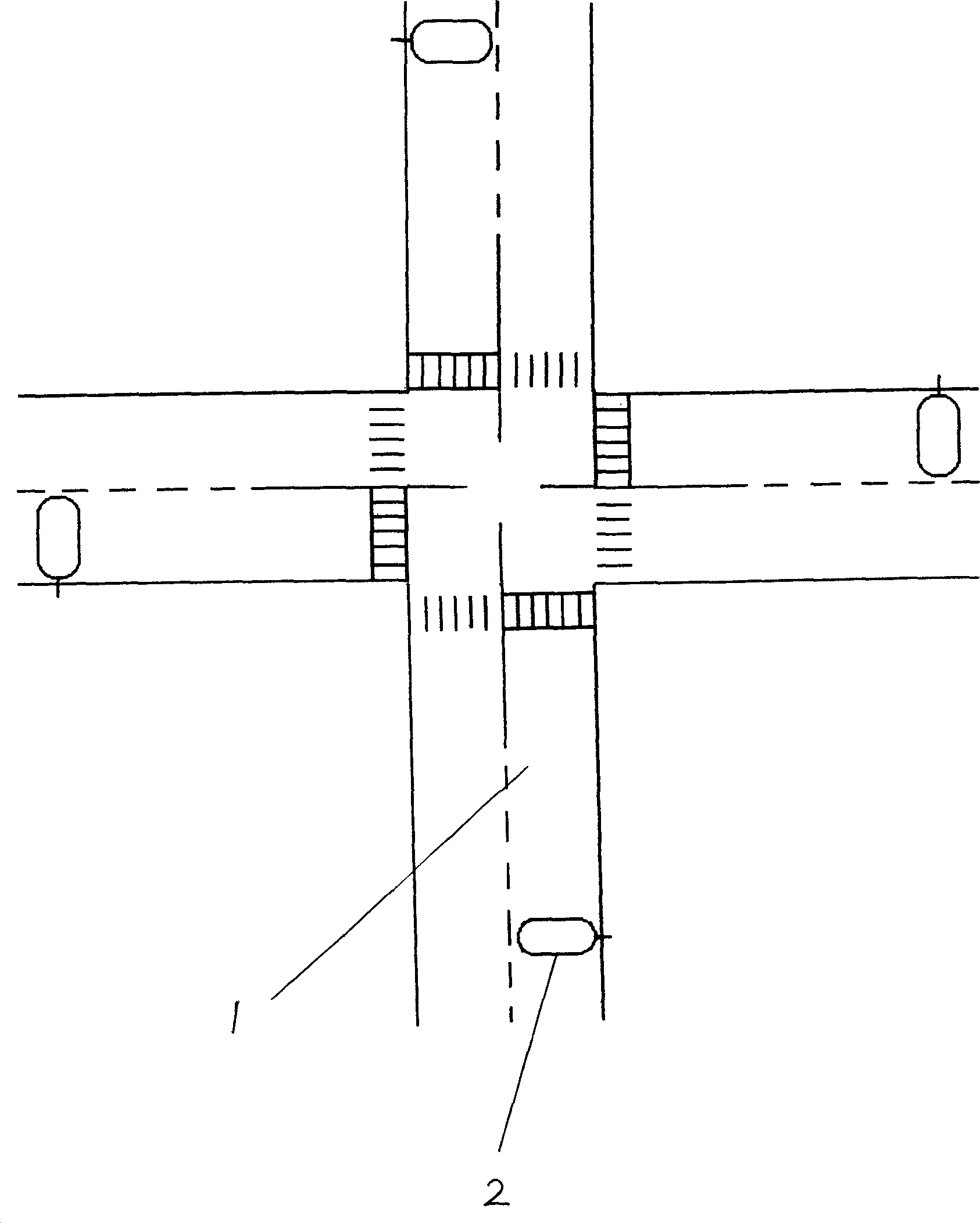
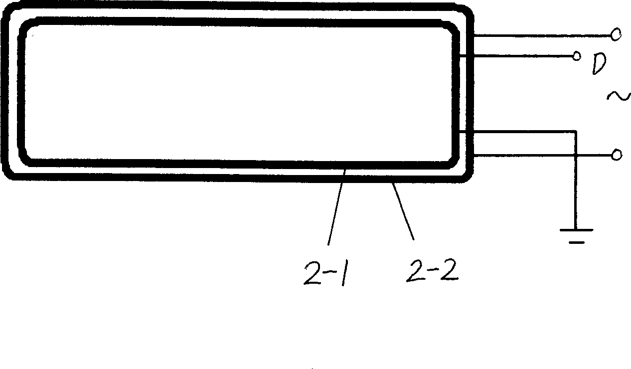
[0012] The present invention includes controller, time display, signal indicator light in original system, in addition, with reference to figure 1 and figure 2 , the traffic flow sensor 2 is set on the road 1, and the embodiment adopts a mutual induction coil, which is composed of two coils, which is equivalent to a transformer, wherein the primary coil 2-2 is connected to the AC power supply, and the secondary coil 2-1 is connected to the input terminal of the identification circuit Connected, when a vehicle passes by, since the vehicle is made of ferrous material, the magnetic lines of force are affected, and the voltage of the secondary coil 2-1 becomes larger.

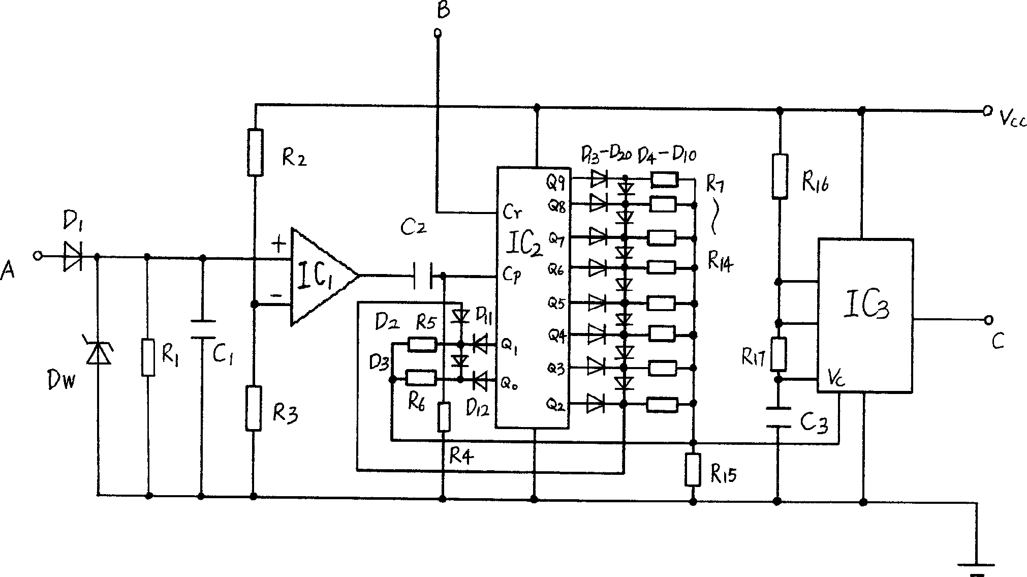
[0013] image 3 , the output terminal D of the secondary coil 2-1 is connected with the voltage comparator IC 1 , Decoder IC 2 The input terminal A of the identification circuit composed of its peripheral components is connected.

[0014] The clock oscillating circuit in the controller adopts an adjustable fre...


PUM


Abstract

A traffic light system automatically adjusting according to the flow of vehicles includes a controller, a time display and a signal indicator light in the original system, a flow sensor is set on the road connected with an identification circuit, the clock oscillator circuit in the controller is applied with an frequency modulated oscillation circuit with its control end connected with the output end of the identification circuit and the vehicle flow sensor tests the number of vehicles, oscillation frequencies of the clock oscillation circuit in the controller and controls the signal switch time at the cross to reach the aim of arranging the waiting time of vehicles reasonably and fully utilize the traffic resources.

Description

technical field [0001] The invention relates to a traffic signal control device, especially an improvement to a traffic light system. Background technique [0002] The existing traffic light system includes a controller, a time display, and a signal indicator light, wherein the controller is composed of a clock oscillating circuit, a timing sequence switching circuit, and an output circuit, or a single-chip microcomputer control circuit is used to combine the clock oscillating circuit and timing sequence switching circuit It is concentrated in the single-chip microcomputer, and is connected with the time display and the signal indicator light through the output circuit. By calculating the clock pulse signal, it is displayed on the time display, and the indicator signal is switched on time to control the driving. In the current system, the switching time is fixed. When the number of vehicles on the road varies, it is easy to cause unreasonable allocation, waste of road resou...

Claims


Application Information

Patent Timeline
IPC IPC(8): G08G1/08G08G1/042
Inventor 朱汪逸
Owner 朱汪逸
Why Eureka
Try Eureka