Image display device and projector

An image display device and a technology for displaying images, which are applied in the field of optical structures, can solve the problems of image quality deterioration, display image image quality deterioration and the like, and achieve the effect of reducing moire fringes

Inactive Publication Date: 2006-04-19
SEIKO EPSON CORP
View PDF5 Cites 21 Cited by
  • Summary
  • Abstract
  • Description
  • Claims
  • Application Information

AI Technical Summary

Problems solved by technology

[0013] However, for the image display device of the above-mentioned structure, since the optical image formed by the first light modulation element is transmitted to the second light modulation element, optical overlap between the pixel patterns of each light modulation element sometimes occurs. Picture quality degradation caused by
[0014] For example, when the first and second light modulators have light-shielding patterns (black stripes, black matrices, etc.) with a periodic structure, moiré fringes will occur due to slight misalignment between the two, deteriorating the picture quality of the displayed image.

Method used


Image

  • Image display device and projector
  • Image display device and projector
  • Image display device and projector

Examples


no. 1 Embodiment approach

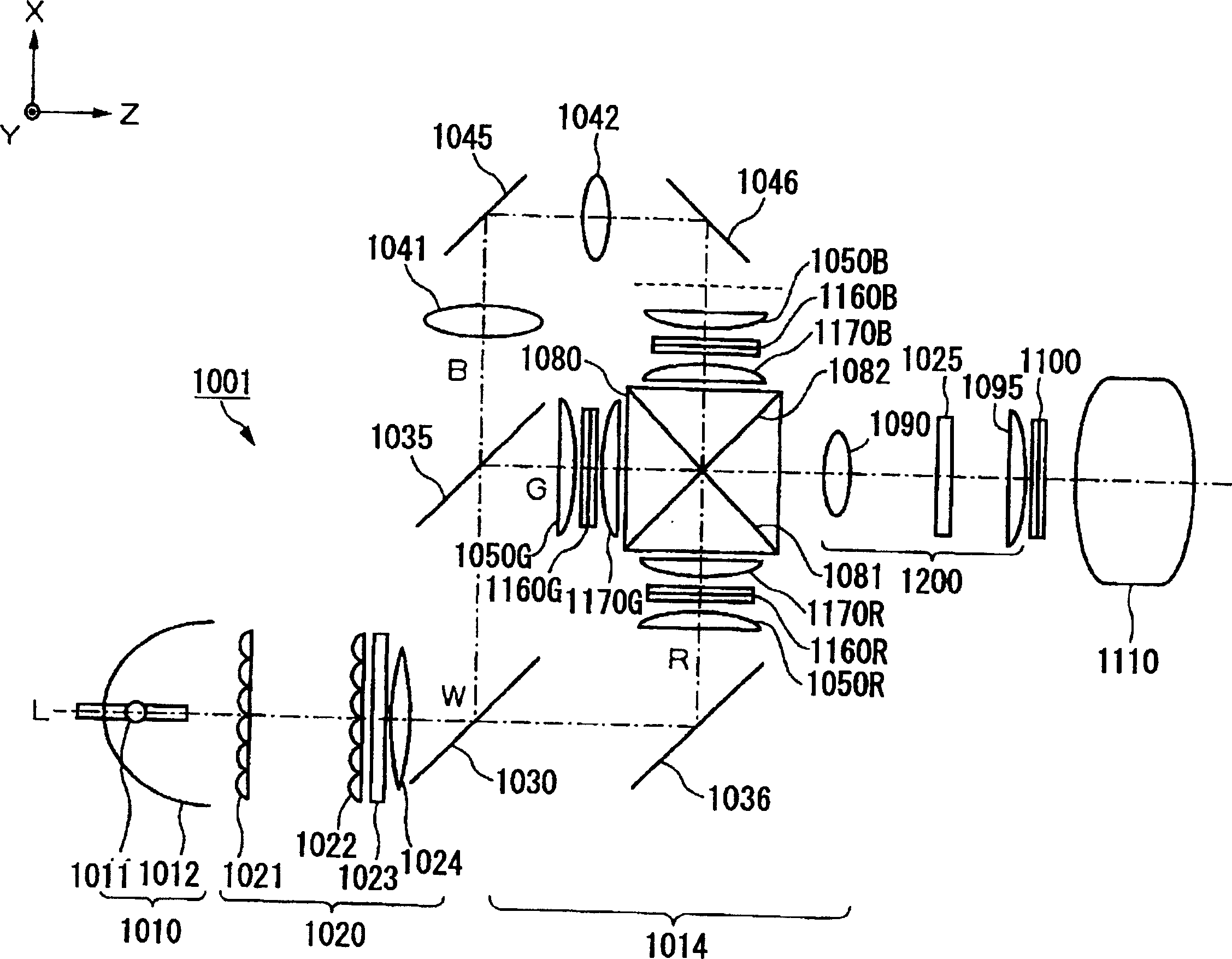
[0108] exist figure 1 Among them, the projection display device involved in this embodiment includes: a light source 1010; a uniform illumination mechanism 1020, which is used to uniformize the brightness distribution of the light incident from the light source 1010; a color modulation unit 1014, which is used to uniformly illuminate the The brightness of the RGB three primary colors in the wavelength region of the light incident by the mechanism 1020 is respectively modulated; the relay lens 1200 is used to relay the light incident from the color modulation part 1014; the brightness modulation liquid crystal light valve 1100 is used to modulating the brightness of the light incident from the relay lens 1200 in the full wavelength region; and a projection lens 1110 for projecting the light incident from the brightness modulating liquid crystal light valve 1100 onto a screen (not shown).

[0109] The light source 1010 is composed of a lamp 1011 such as a high-pressure mercury l...

no. 2 Embodiment approach

[0171] Next, an image display device according to a second embodiment of the first aspect of the present invention will be described. Since the schematic configuration of the image display device is basically the same as that of the first embodiment, the same reference numerals are assigned to the same components as those of the first embodiment, and overlapping descriptions thereof will be omitted.

[0172] In addition, the said Figure 19 The three-dimensional structure of main parts of the prism group 1240 functioning as a low-pass filter in the image display device according to the second embodiment of the first aspect of the present invention is shown.

[0173] The prism group 1240 is composed of two sets of prism elements 1241a and 1241b. The prism element 1241a has a substantially trapezoidal cross-sectional shape in the y-axis direction which is the first direction. In addition, the prism element 1241a has a longitudinal direction in the x-axis direction as the secon...

no. 3 Embodiment approach

[0191] Next, an image display device according to a third embodiment of the first aspect of the present invention will be described. Since the schematic structure of the image display device according to the third embodiment of the first aspect of the present invention is basically the same as that of the first embodiment, the same parts as those of the first embodiment are given the same reference numerals, and the overlapping descriptions are given. omitted.

[0192] Figure 23 A cross-sectional structure of main parts of the prism group 1280 functioning as a low-pass filter in the image display device according to the third embodiment of the first aspect of the present invention is shown.

[0193] In the prism group 1280, the two refraction surfaces 1280a form periodic V-shaped grooves. There is only a distance d between the reference surface 1281 and the flat portion 1280b, which is formed at the intersection point between the refractive surface 1280a and the optical axi...


PUM

PropertyMeasurementUnit
refractive indexaaaaaaaaaa

Abstract

An image display device modulates light from a light source according to display image data and displays an image, and includes a first light modulation element that modulates light from the light source, a second light modulation element that modulates light from the first light modulation element, and an illumination optical system that leads a light beam, which has been modulated by the first light modulation element, to the second light modulation element; the illumination optical system comprising an optical element that spectrally illuminates a light beam from the first light modulation element to the second light modulation element at a predetermined position, the optical element being provided between the first light and second light modulation elements and the optical element including a prism group including prism elements, each prism element including a refractive surface that refracts an incident light in a predetermined direction.

Description

technical field [0001] The present invention relates to image display devices such as projectors. In addition, the present invention relates to a technique for improving picture quality of an image display device, and particularly relates to an optical structure suitable for realizing expansion of a dynamic range of display brightness and high gray scale. Background technique [0002] In recent years, image display devices have been required to have higher contrast, and expectations for high-contrast projectors are increasing. Therefore, it is imperative to realize a projector with high picture quality and high contrast ratio. [0003] Moiré fringes are generated as a problematic characteristic in an image display device having two spatial modulation elements, a first regularly arranged spatial modulation element and a second regularly arranged spatial modulation element. Moiré fringes are characterized by overlapping of two or more regular patterns. By making one of the r...

Claims


Application Information

Patent Timeline
Patent Type & Authority Applications(China)
IPC IPC(8): G02B27/18G02F1/13G03B21/00
Inventor 上岛俊司中村旬一内山正一新田隆志旭常盛
Owner SEIKO EPSON CORP
Why Eureka
Try Eureka