Insulation blocking equipment for Ethenret

An isolation protection, Ethernet technology, applied in data exchange network, branch long-distance connection/disconnection, data exchange details, etc., can solve problems such as equipment failure to maintain, network communication interruption, economic loss, etc., to prevent large areas of lightning damage effect

Inactive Publication Date: 2006-04-19
徐震
View PDF0 Cites 3 Cited by
  • Summary
  • Abstract
  • Description
  • Claims
  • Application Information

AI Technical Summary

Problems solved by technology

The current network devices are often connected by wires. In the thunderstorm season, once a device is struck by lightning, a huge current will be transmitted along the wires to all the devices connected to it, destroying these devices and causing network communication problems. Interruption, paralysis of Ethernet functional equipment and Ethernet terminal equipment, and huge economic losses because the destroyed equipment cannot be repaired
At present, most Ethernet lightning protection adopts the method of discharging the signal line to the ground, which cannot solve the damage caused by the high potential difference between the two devices.

Method used


Image

  • Insulation blocking equipment for Ethenret
  • Insulation blocking equipment for Ethenret
  • Insulation blocking equipment for Ethenret

Examples


Embodiment 1

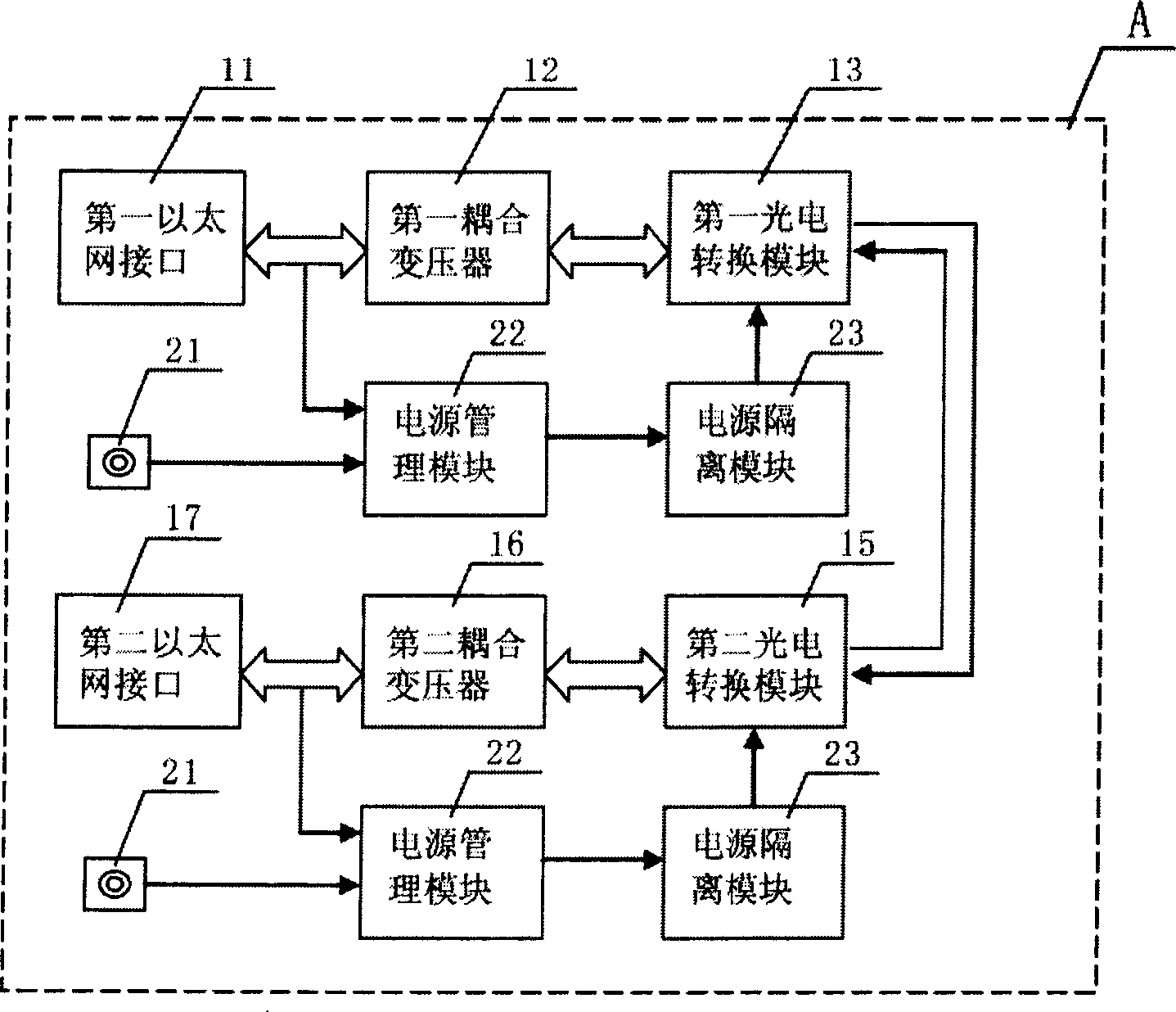
[0014] figure 2 It is a block diagram of an embodiment of the Ethernet isolation protection device of the present invention. The Ethernet isolation and protection device A of the present invention includes: a first Ethernet interface 11, which is characterized in that it also includes: a first coupling transformer (FC-518LS) 12, which is used to use the first Ethernet interface 11 The Ethernet signal at the terminal is coupled to the first photoelectric conversion module 13 through the conversion of the electromagnetic field; the first photoelectric conversion module 13 uses an optocoupler or an optical terminal to convert the differential signal from the coupling transformer into an optical signal and outputs it to the second Photoelectric conversion module; the second photoelectric conversion module 15 converts the optical signal from the first photoelectric conversion module into a differential signal and transmits it to the second coupling transformer 16; the second coupl...

Embodiment 2

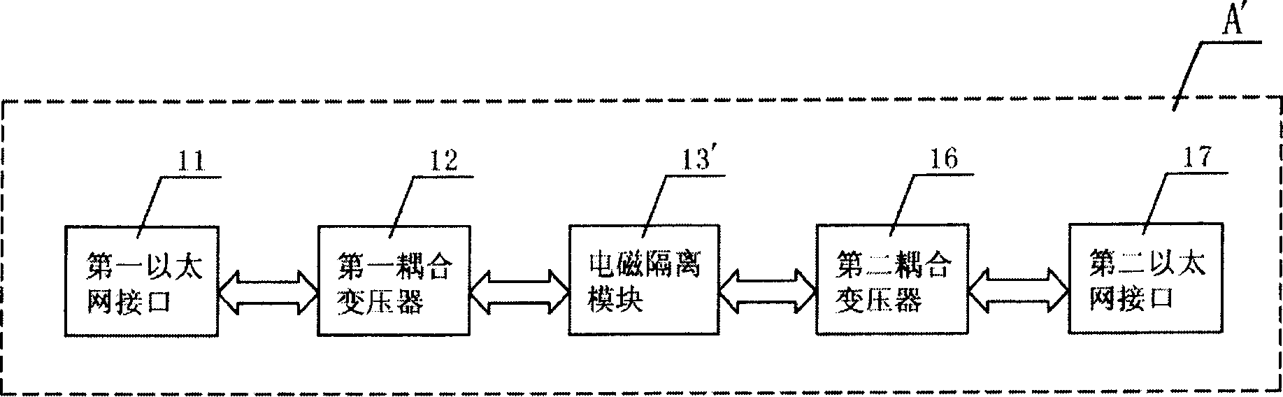
[0016] image 3 It is a block diagram of another embodiment of the Ethernet isolation protection device of the present invention. In this figure, the same parts as those of the first embodiment described above are given the same symbols.

[0017] The Ethernet isolation and protection device B of the present invention includes: a first Ethernet interface 11, which is characterized in that it also includes: a first coupling transformer 12, which is used to convert the Ethernet signal at the Ethernet interface end to Through the conversion of the electromagnetic field, it is coupled to the electromagnetic isolation module 13' (NVE-IL716) described later; the electromagnetic isolation module 13' converts the differential signal into a magnetic field signal and simultaneously converts the magnetic field signal into a differential signal and transmits it to the second coupling transformer 16; The second coupling transformer 16 transmits the differential signal from the electromagne...


PUM


Abstract

The equipment includes following parts: first Ethernet interface; through conversion of electromagnetic field, first coupling transformer in use for coupling Ethernet signal at Ethernet interface end to the following photovoltaic conversion module; first photovoltaic conversion module converts differential signal from the coupling transformer to optical signal; second photovoltaic conversion module in use for converting optical signal from first photovoltaic conversion module to differential signal, which is sent to second coupling transformer; second coupling transformer sends differential signal from second photovoltaic conversion module to second Ethernet interface through coupling mode. Using mode of optical isolation or magnetic isolation, the invention isolates electrical connection between network devices thoroughly so as to prevent network devices in larger area from shot up caused by thunder.

Description

technical field [0001] The invention relates to a protection device for network communication, in particular to a protection device for protecting Ethernet functional equipment and Ethernet terminal equipment by means of isolation. Background technique [0002] With the advancement of science and technology, the information age has arrived, and information technology has penetrated into all fields of production and life in human society. The network is the carrier of information, and Ethernet functional devices play a "hub" role in network data transmission. The current network devices are often connected by wires. In the thunderstorm season, once a device is struck by lightning, a huge current will be transmitted along the wires to all the devices connected to it, destroying these devices and causing network communication problems. Interruption, paralysis of Ethernet functional equipment and Ethernet terminal equipment, and huge economic losses because the destroyed equipm...

Claims


Application Information

Patent Timeline
Patent Type & Authority Applications(China)
IPC IPC(8): H04L12/24H04L12/12
CPCY02B60/35Y02D30/50
Inventor 徐震
Owner 徐震
Why Eureka
Try Eureka