Electronic controlled valve arrangement

A valve device, electronic control technology, applied in the direction of brakes, etc., can solve problems such as damage to the exhaustability of the braking system, and achieve the effects of avoiding blockage, high adjustment accuracy, and reliable exhaustability.

Inactive Publication Date: 2010-05-26
ROBERT BOSCH GMBH
View PDF7 Cites 0 Cited by
  • Summary
  • Abstract
  • Description
  • Claims
  • Application Information

AI Technical Summary

Problems solved by technology

In particular, if in this position even the non-return valve in the bypass is in its closed position, the reliable ventability of the brake system is impaired.

Method used


Image

  • Electronic controlled valve arrangement
  • Electronic controlled valve arrangement
  • Electronic controlled valve arrangement

Examples


Embodiment Construction

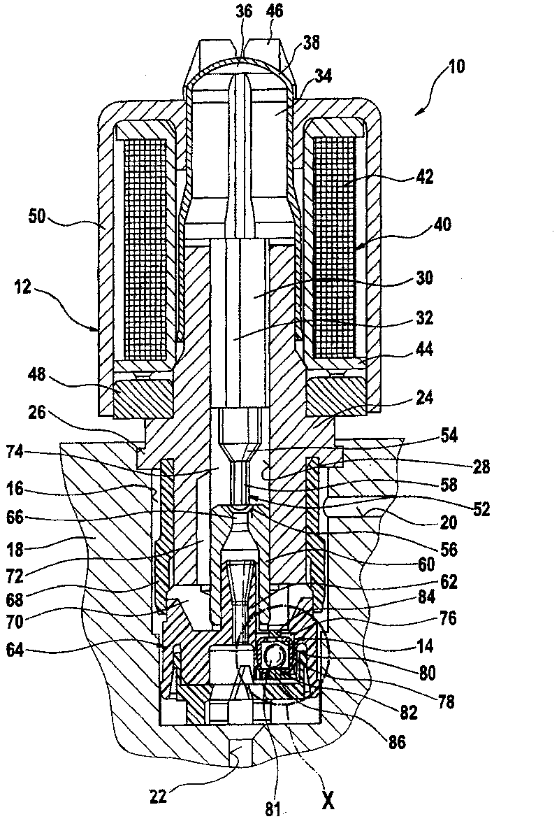
[0016] figure 1 The valve arrangement 10 shown consists of a solenoid valve 12 in which a non-return valve 14 is integrated. The valve device 10 is partly inserted in a mounting chamber 16 of a valve body 18 of a so-called hydraulic unit and is fixed therein in a form-fitting manner by pressing the material of the valve body 18 . Pressure medium channels 20 , 22 are provided in the valve body 18 , which open into the installation cavity 16 of the valve unit 10 for connection to the valve device 10 . A pressure medium channel 20 arranged horizontally in the housing forms the inlet, a vertically arranged pressure medium channel 22 forms the outlet of the valve device 10 . Both pressure medium channels 20 , 22 are sealed against each other with the valve unit 10 installed and sealed against the environment.

[0017] The valve device 10 also includes a valve seat body 24 . In this case it is preferably a pivoting part made of metal, which has a turned radial flange 26 for pres...


PUM


Abstract

The invention relates to an electronically controlled valve device (10), which is particularly used for automobile brake devices. The prior valve device (10) includes an electromagnetic valve (12) anda valve member (52) with the free motion is used for controlling a valve seat (56) which is arranged between pressure medium channels (20, 22). A hydraulic bypass bypasses the valve seat (56). A one-way valve (14) is arranged in the bypass. When in vacuum pumping of the brake system, the valve member (52) of the electromagnetic valve (12) is pulled to the upper surface of the valve seat (56) andthe continuous vacuum pumping of the brake system can be prevented. The valve device (10) of the invention can solve the problem. Thus, the one-way valve is provided with a through one-way valve outershell (78), which is provided with valve holes (80, 82) which are distributed on the opposite ends, and the valve holes are controlled by a common valve member (81). The one-way valve (14) can be relatively fixed on the electromagnetic valve (12) by motion and be loaded and fixed on a terminal position by pressure. When in non-fixed state, the one-way valve (14) and a latch-up protection device (84) act commonly, and the protection device prevents the one-way valve (14) getting to the latch-up position.

Description

technical field [0001] The invention relates to an electronically controllable valve arrangement. Background technique [0002] A valve arrangement of this type is known, for example, from DE 19635693 A1. This known valve arrangement consists of a solenoid valve and an integrated non-return valve. of the above documents figure 2 The solenoid valve shown in has a seat body in which a freely moving plunger is guided for longitudinal movement. The push rod cooperates with an armature, and an excitation coil acts on the armature. Depending on the energization of the field coil, a magnetic field is generated which forces the armature to travel. This stroke is transmitted by the plunger to a valve member that controls the valve seat. The valve seat is located between an inlet and an outlet of the solenoid valve. A pressure medium connection designed as a bypass bypasses the valve seat. This pressure medium connection is controlled by a non-return valve. For this purpose, t...

Claims


Application Information

Patent Timeline
Patent Type & Authority Patents(China)
IPC IPC(8): B60T8/36
CPCB60T8/363B60T8/34B60T8/341
Inventor S·阿卡
Owner ROBERT BOSCH GMBH
Why Eureka
Try Eureka