Hood stopper structure for automobile
A technology of engine cover and stopper, which is applied in the directions of superstructure, vehicle components, and subassembly of superstructure, and can solve problems such as complex structure and so on.
- Summary
- Abstract
- Description
- Claims
- Application Information
AI Technical Summary
Problems solved by technology
Method used
Image
Examples
Embodiment approach 1
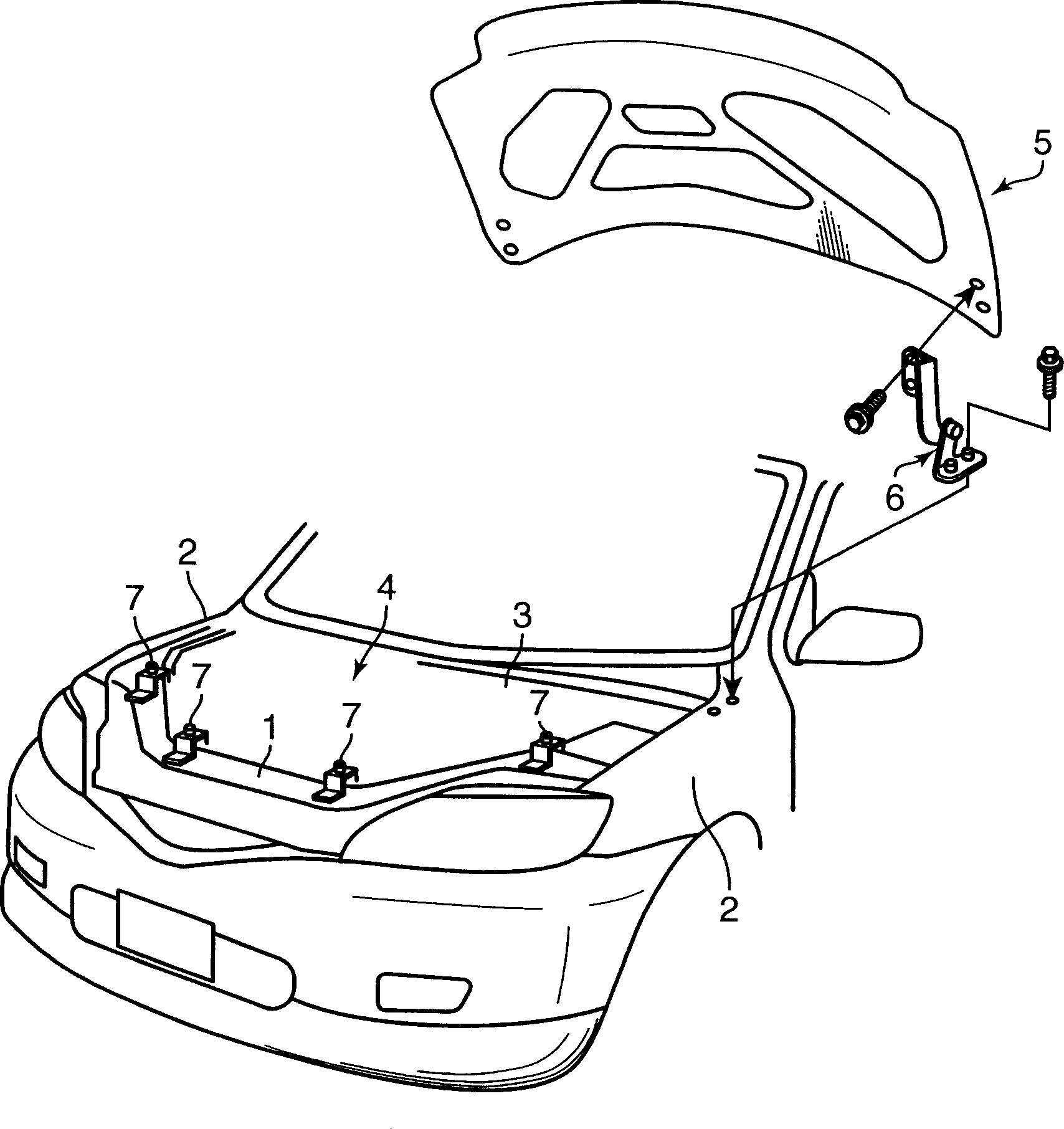
[0073] figure 1 Shown is a front vehicle body having a vehicle hood stopper structure of the present invention. A hood 5 for opening and closing the upper end opening of the engine compartment 4 is provided on the front front body. It is surrounded by a front fender panel (front fender panel) 2 at the top and a dash panel (dash panel) 3 at the rear.
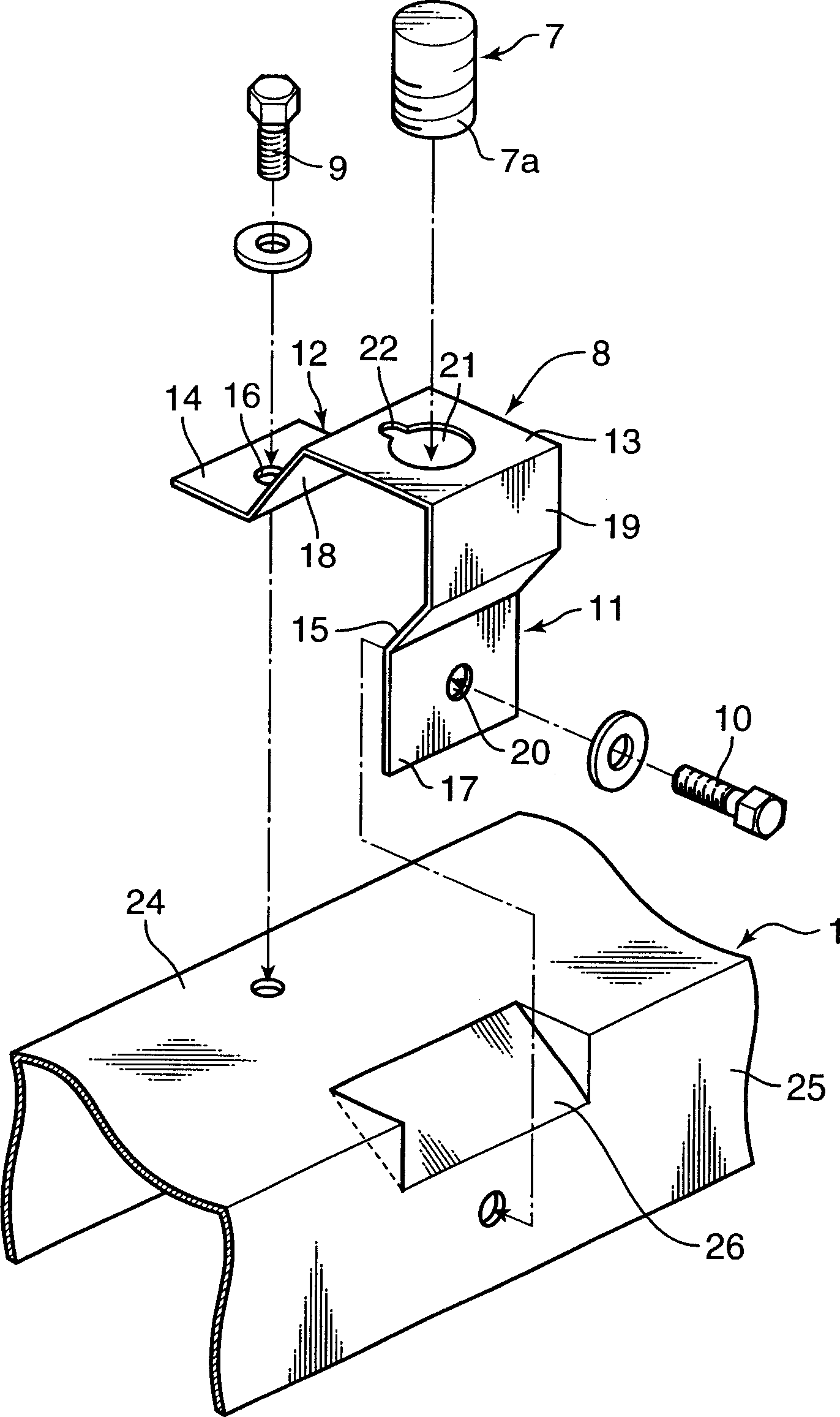
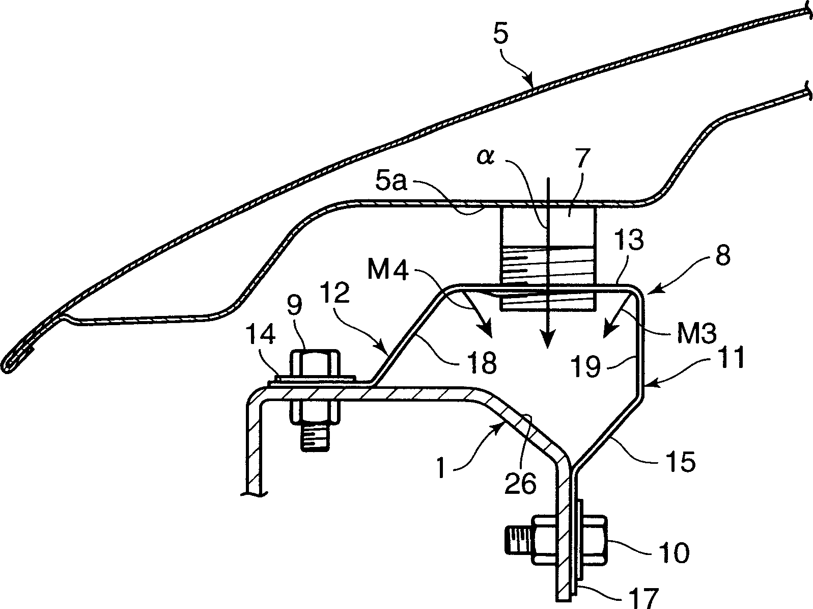
[0074] The engine cover 5 can be operated by swinging the engine cover hinge 6 provided between the lower side of the rear end portion and the upper surface of the rear end portion of the front fender 2 as a fulcrum, so that the upper opening of the engine room 4 can be opened. Changes between the two states of closed or open are possibly supported. In addition, between the lower surface of the front end portion of the hood 5 and the upper surface of the front cover 1, an engine hood locking device (not shown) is provided to keep the hood 5 in a closed state, and the front cover 1 1 are provided with stoppers 7 that function a...
Embodiment approach 2
[0095] Figure 9 A second embodiment of the present invention is shown in which the lower end portion of the first leg portion 11 of the support bracket 8 is fixed to the rear upper surface of the cowl panel 1 . In the second embodiment, when the engine cover 5 is closed, the stopper 7 supported by the support bracket 8 is prevented from being plastically deformed by preventing the first and second leg portions 11, 12 of the support bracket 8 from being plastically deformed. Elastic deformation can absorb the impact energy generated when the engine cover 5 is closed, and in the event of a collision accident in which a pedestrian's head hits the engine cover 5, etc., a certain value or more of the load will move along the direction from the oblique front upper side to the rear lower side. When the inclined direction β acts on the support bracket 8, the first and second leg portions 11, 12 of the support bracket 8 are plastically deformed, as shown by the arrow γ, so that the su...
Embodiment approach 3
[0097] Figure 10 A third embodiment of the vehicle hood stopper structure of the present invention is shown. In this third embodiment, the first leg portion 51 of the support bracket 8 is along the input direction β( Figure 11 ) is inclined rearward and downward, and the rear wall portion 27 of the cowl panel 1 is constituted by an inclined surface inclined corresponding to the angle of the first leg portion 51 .
[0098] On the rear portion of the first foot portion 51 upper end portion of the support bracket 8 and the top plate portion 13, a long hole-shaped first slot 32 communicating with the rear edge portion of the support hole 21 of the embedded stopper 7 is formed. The top plate portion 13 is formed with a second slot 33 formed of a U-shaped cutout communicating with the front edge portion of the support hole 21 . Also, on the first leg portion 51 of the support bracket 8, above the through hole 20 (the through portion through which the rod-shaped member can pass) ...
PUM
 Abstract
Description
Claims
Application Information
 - R&D
- Intellectual Property
- Life Sciences
- Materials
- Tech Scout
- Unparalleled Data Quality
- Higher Quality Content
- 60% Fewer Hallucinations
Browse by: Latest US Patents, China's latest patents, Technical Efficacy Thesaurus, Application Domain, Technology Topic, Popular Technical Reports.
© 2025 PatSnap. All rights reserved.Legal|Privacy policy|Modern Slavery Act Transparency Statement|Sitemap|About US| Contact US: help@patsnap.com


