Transformer of converter

A technology of transformers and inverters, applied in the field of transformers, can solve the problems of inability to cope with the increasing size of LCD panels and uneven brightness at both ends of the lamp tube, so as to eliminate uneven brightness, improve stability and reliability, and uniform backlight. effect of light source

Inactive Publication Date: 2006-04-26
YAO SHENG ELECTRONICS +1
View PDF0 Cites 3 Cited by
  • Summary
  • Abstract
  • Description
  • Claims
  • Application Information

AI Technical Summary

Problems solved by technology

[0005] 1. Unable to cope with the increasing trend of LCD panel size
[0006] 2. The brightness of the high voltage side is always slightly higher than that of the ground side
[0007] 3. It is easy to cause uneven brightness at both ends of the lamp tube

Method used


Image

  • Transformer of converter
  • Transformer of converter
  • Transformer of converter

Examples


Embodiment Construction

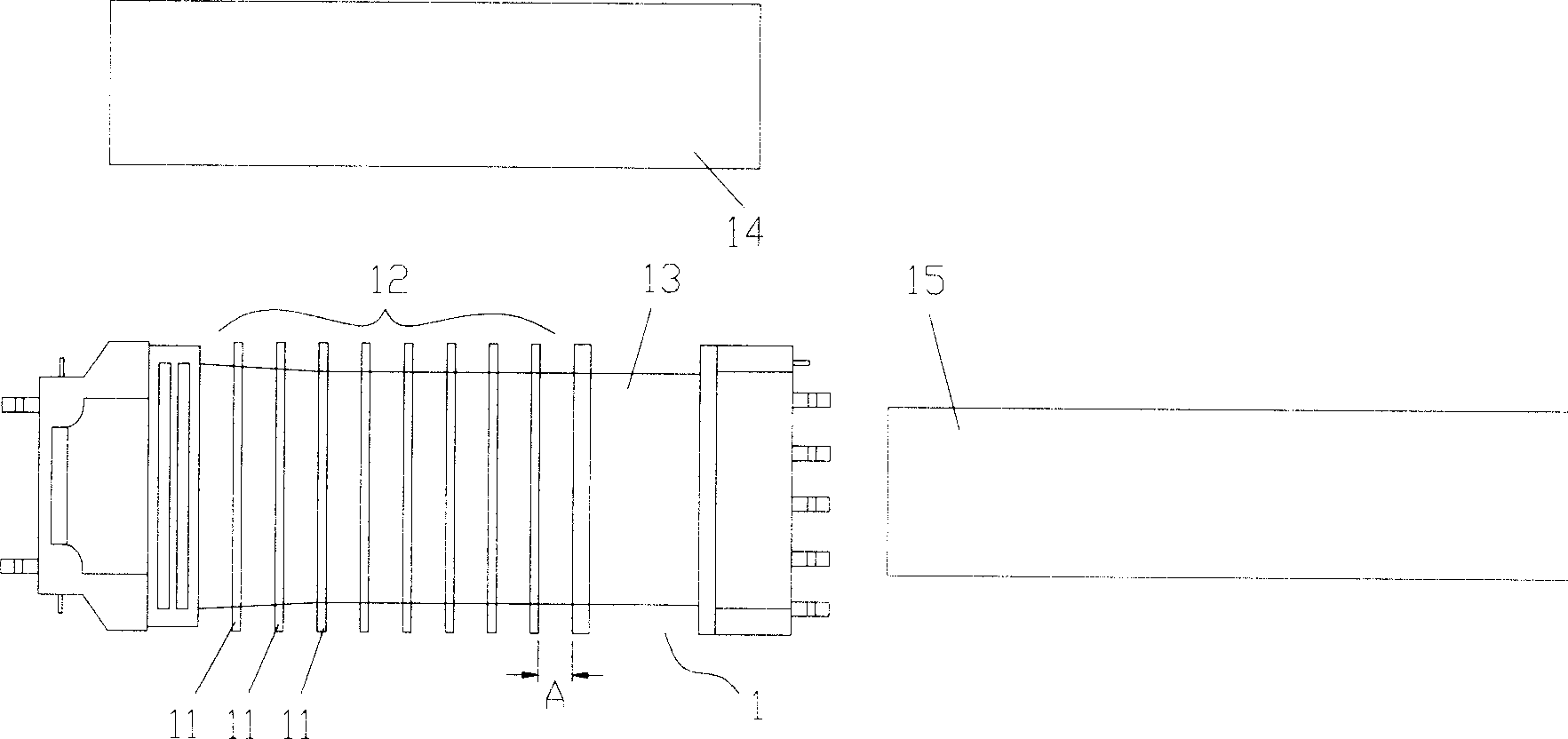
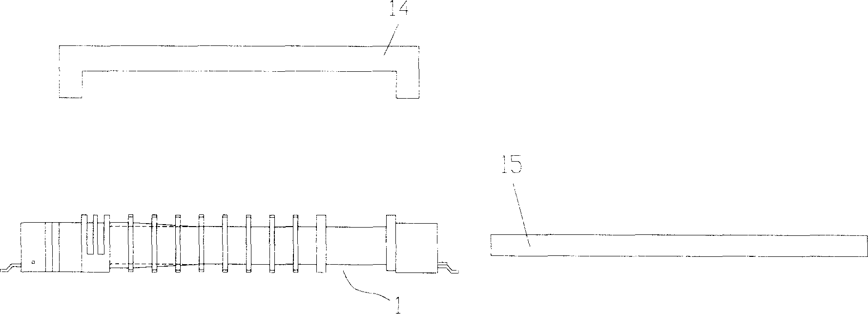
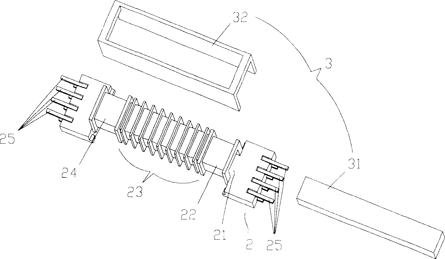
[0039] The invention provides a transformer of a converter, (see image 3 shown), which includes a bobbin frame 2 and a core group 3, wherein the bobbin frame 2 has a hollow portion 21, and a first winding portion 22, a second winding portion 22, and a second winding portion for coil winding are distinguished on its side edge. A wire part 23 and a third winding part 24, and a plurality of lead terminals 25 are provided at both ends of the winding frame 2 to connect with an external circuit;

[0040] The core group 3 has a first core part 31 and a second core part 32, which are respectively assembled in the hollow part 21 and the outside of the winding frame 2, and can be combined to cover the winding frame 2 to form a main magnetic circuit;

[0041] By the above structure (see Figure 4 shown), the primary side excitation coil winding 5 can be independently wound on the first winding part 22 and the third winding part 24 at both ends of the bobbin 2, and the secondary side i...


PUM


Abstract

The invention provides a voltage transformer of current changer. Wherein, making two ends of winding frame to coil the primary side excitation winding independently; arranging the secondary induction winding in the primary side excitation winding; making said two windings couple and stabilize the output of induced voltage to drive one or more CCFL simultaneously. This invention can improve stability and reliability, and then obtain more even backlight light source.

Description

technical field [0001] The present invention is a transformer for a converter, especially a transformer used in a converter module that needs to obtain a 180-degree voltage phase output or multiple sets of output converters. Background technique [0002] According to the general LCD panel, a discharge lamp such as a cold cathode fluorescent lamp (CCFL) is used as the back light of the panel, and these discharge lamps are driven by an inverter circuit , and in order to meet the requirements of high voltage output, it is usually driven by a converter transformer; [0003] Such as figure 1 , figure 2 As shown, they are an exploded top view and an exploded side view of a general existing converter transformer, wherein the existing transformer is mainly composed of a bobbin (Bobbin) 1, a first iron core 14 and a second iron core 15, A plurality of separation grooves 11 are protruded from the side edge, and the primary side winding area 13 and the secondary side winding area 1...

Claims


Application Information

Patent Timeline
Patent Type & Authority Applications(China)
IPC IPC(8): H01F30/00H01F27/24H01F27/28
Inventor 张君毅陈其铭
Owner YAO SHENG ELECTRONICS
Why Eureka
Try Eureka