Liquid drop discharge head, liquid drop discharge device, and image forming device

A technology of imaging device and discharge device, applied in the direction of inking device, printing, piezoelectric device/electrostrictive device, etc., which can solve the problems of high cost of printer and high burden of collecting lead

Inactive Publication Date: 2006-05-10
RICOH KK
View PDF3 Cites 5 Cited by
  • Summary
  • Abstract
  • Description
  • Claims
  • Application Information

AI Technical Summary

Problems solved by technology

In addition, because the discharge head parts are mechanically positioned with extremely high precision, the cost of disassembling the printer is also high
Because of this, the burden on manufacturers to collect lead is also extremely high

Method used


Image

  • Liquid drop discharge head, liquid drop discharge device, and image forming device
  • Liquid drop discharge head, liquid drop discharge device, and image forming device
  • Liquid drop discharge head, liquid drop discharge device, and image forming device

Examples


Embodiment Construction

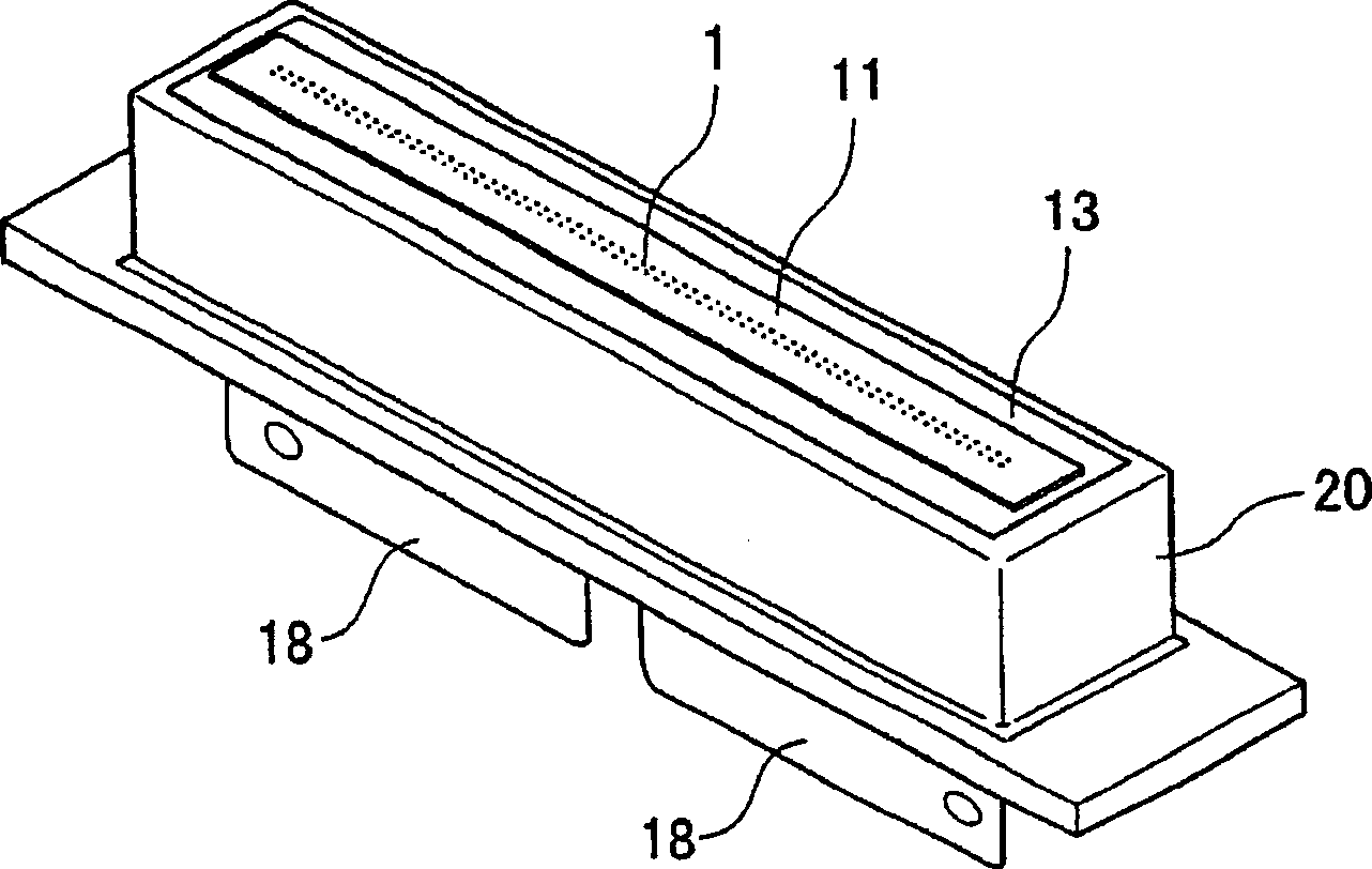
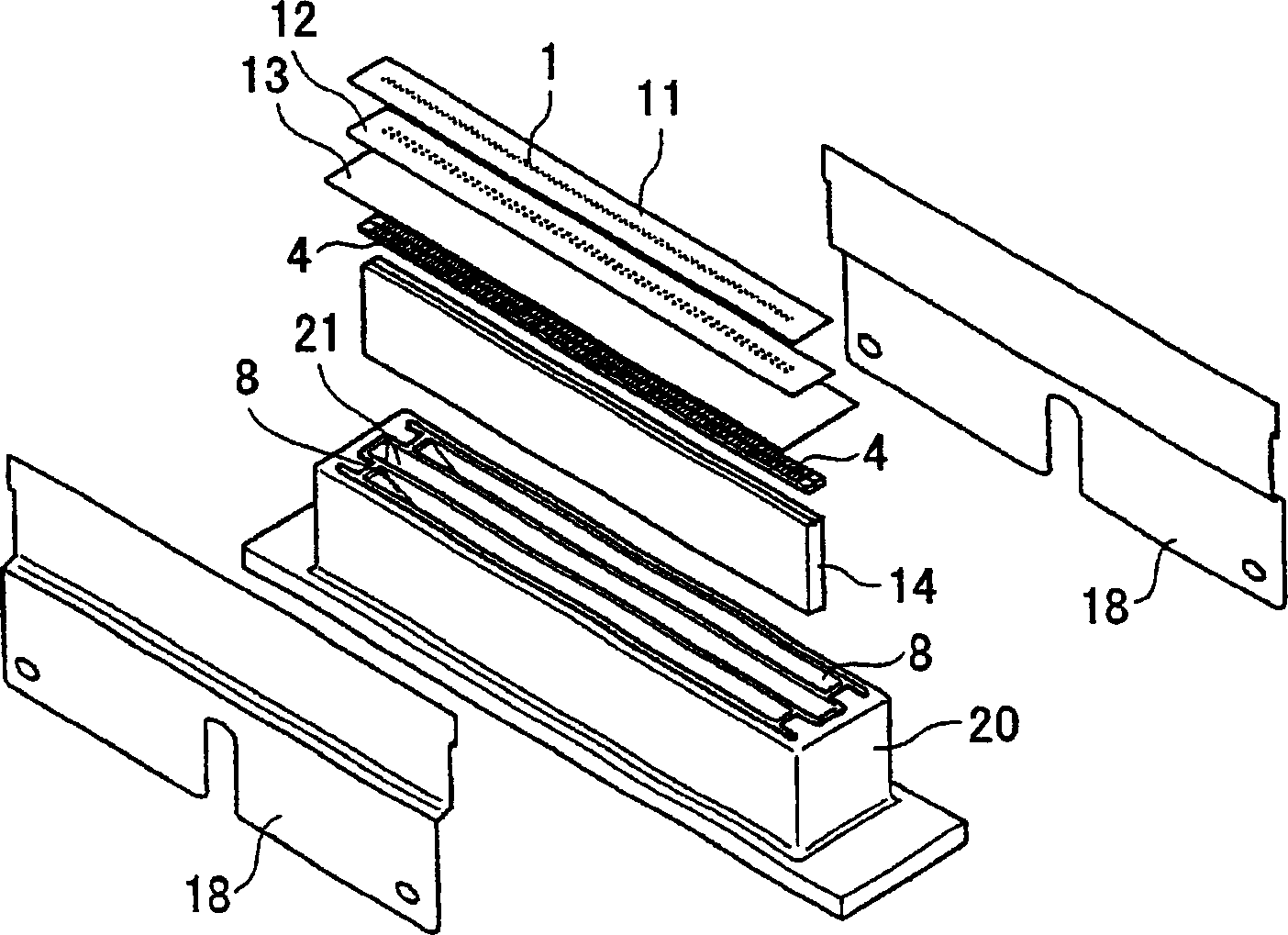
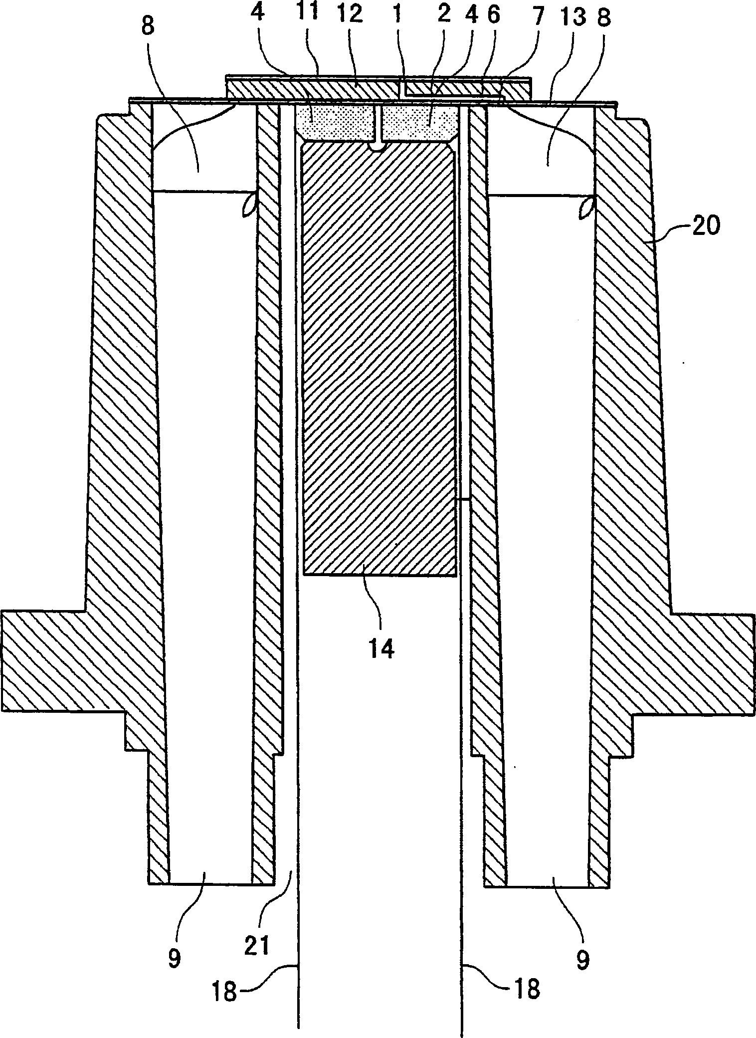
[0030] Reference is now made to the figure 1 - Figure 7 gives a description of the invention and details of the disadvantages of the related art. First, refer to Figure 1-Figure 3 A first embodiment of the droplet discharge head of the present invention will be discussed. figure 1 is a perspective view of the outside of the droplet discharge head. figure 2 is an exploded perspective view of the droplet discharge head. image 3 is a sectional view of the droplet discharge head.

[0031] The liquid drop discharge head has: a nozzle 1 for discharging liquid droplets; a pressure chamber 2 connected to the nozzle 1; a vibrating plate 3 (not shown) forming a side part of the pressure chamber 2; a piezoelectric element 4, the pressure chamber 2 The electrical element 4 can serve as an actuator device, such as a pressure generating device or a drive device that compresses the liquid in the pressure chamber 2 via the vibrating plate 3 . The droplet discharge head also has a comm...


PUM


Abstract

A liquid drop discharge head includes nozzles that discharge liquid droplets using piezoelectric elements. There is no lead component in the piezoelectric element.

Description

technical field [0001] The present invention relates to a liquid drop discharge head, a liquid drop discharge device, and an image forming device. Background technique [0002] As an image forming apparatus, an inkjet recording apparatus having a droplet discharge device including a droplet discharge head is known, such as a printer, a facsimile, a copier and a printer, facsimile, copier multifunction device. [0003] In an inkjet recording apparatus, droplets of a recording liquid are ejected from a recording head onto a recording medium such as paper, OHP (Overhead Projector) film, recording medium, or recording paper, thereby enabling imaging such as recording, printing, or reproduction. It is possible to record a high-precision image at high speed on a recording medium by an inkjet recording device. In addition, the running cost is cheap and the noise is small in the inkjet recording apparatus. Furthermore, in an inkjet recording device, a color image can be easily rec...

Claims


Application Information

Patent Timeline
Patent Type & Authority Applications(China)
IPC IPC(8): B41J2/045B41J2/055B41J2/14H01L41/09
CPCB41J2/14201B41J2/14274B41J2202/03B41J2/045
Inventor 山口清佐佐木隆文
Owner RICOH KK
Why Eureka
Try Eureka