
Steel pipe in construction structure

A technology for building structures and steel pipes, which is applied to building components, building structures, buildings, etc., can solve problems such as buckling instability damage, application restrictions of thin-walled steel pipes, etc., and achieve the effect of easy operation and low cost

Inactive Publication Date: 2006-05-17
GUANGZHOU UNIVERSITY
View PDF0 Cites 4 Cited by
  • Summary
  • Abstract
  • Description
  • Claims
  • Application Information

AI Technical Summary

Problems solved by technology

[0002] Due to the good tensile properties of steel, it is easy to buckle and fail when it is under pressure, so the application of thin-walled steel pipes in compression members in building structures is limited.

Method used


Image

  • Steel pipe in construction structure
  • Steel pipe in construction structure

Examples


Embodiment Construction

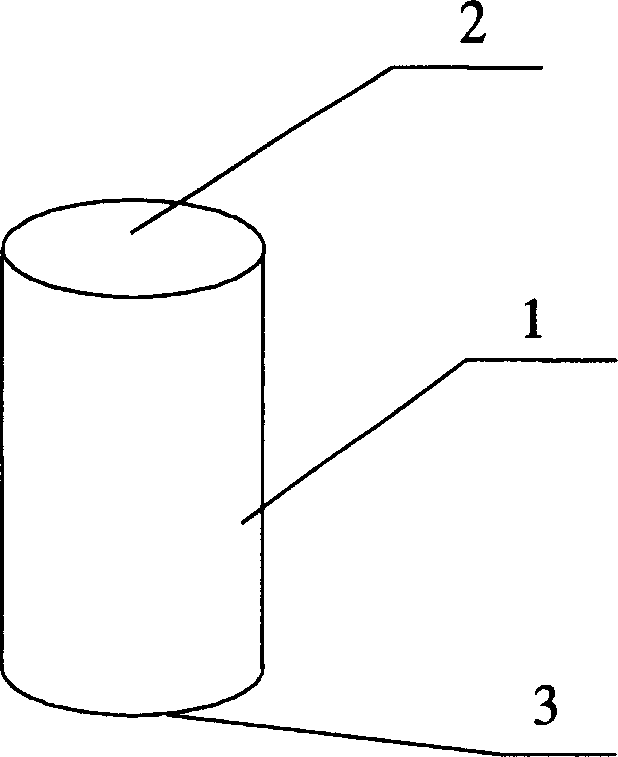
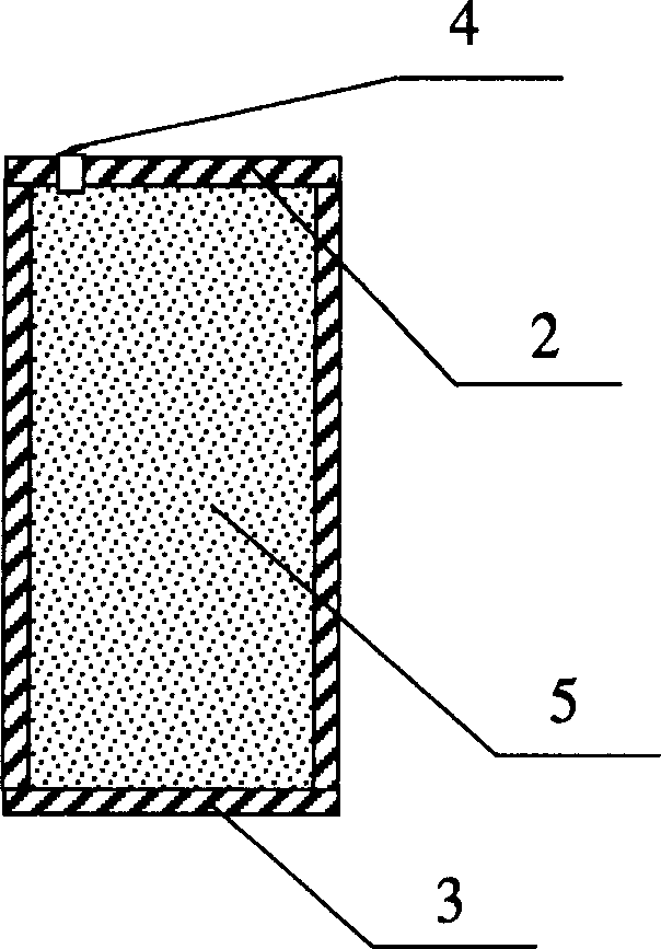
[0014] The steel pipe in the building structure of the present invention is composed of a pipe body 1 and an upper end surface 2 and a lower end surface 3 closed on the upper and lower ends of the pipe body 1 by welding. First seal the two ends of the pipe body 1 by welding and reserve a screw hole 4, then pour water 5 through high pressure to ensure that there is no gas inside, and then seal the screw hole 4.

[0015] The liquid-filled steel pipe can be used as an axial compression member, for example, as a column of a building structure, such an application is to exert force on both end faces of the liquid-filled steel pipe in the axial direction.


PUM


Abstract

The present invention relates to a new-type thin-wall steel pipe in building structure, in particular, it is a liquor-charged steel pipe. Said steel pipe is formed from pipe body and upper end face and lower end face which are welded on the upper and lower ends of said steel pipe respectively and used for closing the upper and lower two ends of said steel pipe. It is characterized by that in the interior of steel pipe the liquor is charged, on the pipe body is set a hole through which the water can be injected into the interior of steel pipe by means of high pressure so as to ensure that in the interior of steel pipe the air is not existed, so that it can raise the bearing capacity of steel pipe.

Description

technical field [0001] The invention relates to a novel thin-walled steel pipe in a building structure, in particular to a liquid-filled steel pipe. Background technique [0002] Since steel has good tensile properties, it is prone to buckling failure when it is under pressure, so the application of thin-walled steel pipes in compression members in building structures is limited. If the two ends of the steel pipe are sealed, a liquid with a small compressibility, such as water, is filled in the steel pipe. When the two ends of the steel pipe are under pressure, the force is transmitted to the liquid through the end plate of the steel pipe, and the liquid has little compressibility. , and the pressure transmission is isotropic, so the wall of the steel pipe will be subjected to the outward pressure of the internal liquid, and it is less likely to be buckled and damaged, thus giving full play to the advantages of the two materials and increasing the bearing capacity of the ste...

Claims


Application Information

Patent Timeline
IPC IPC(8): E04C3/00E04C3/32
Inventor 孙作玉程树良
Owner GUANGZHOU UNIVERSITY
Learn More