Line belt coiling unit for braiding flat-bed machine

A technology of coiling device and conveyor belt, applied in weft knitting, knitting, textiles and papermaking, etc., can solve the problems of large debugging workload, high manufacturing requirements, complex structure and installation process, etc., and achieve convenient installation and debugging, even pulling The effect of pulling force and good coiling effect

Inactive Publication Date: 2006-05-24
冯加林
View PDF1 Cites 8 Cited by
  • Summary
  • Abstract
  • Description
  • Claims
  • Application Information

AI Technical Summary

Problems solved by technology

However, this kind of pulling device has the following disadvantages: at the beginning of weaving, the operator needs to manually operate to guide, pull and take up the woven fabric; Guidance requirements for thick fabrics; in addition, fabric guidance and traction (coiling) are controlled by two motors, increasing production costs
However, this traction device consists of relatively many parts and the overall structure is relatively large, so it is difficult to install it at a position very close to the barrel mouth
However, the closer the coiling device is to the barrel mouth, the better the coiling effect, so it is difficult for the coiling device to meet this requirement.
At the same time, its structure and installation process are relatively complicated, the debugging workload is relatively large, the manufacturing requirements are high, and the cost is also high

Method used


Image

  • Line belt coiling unit for braiding flat-bed machine
  • Line belt coiling unit for braiding flat-bed machine
  • Line belt coiling unit for braiding flat-bed machine

Examples


Embodiment Construction

[0021] The present invention will be further described below in conjunction with the accompanying drawings and embodiments.

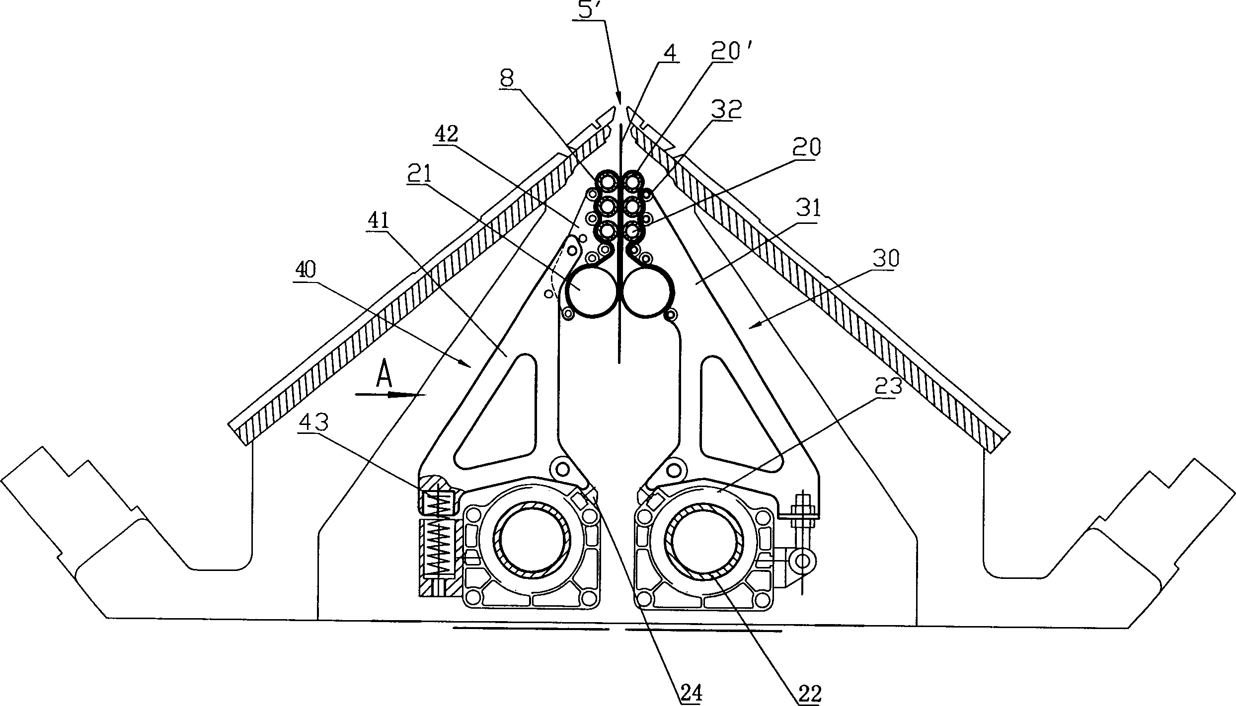
[0022] control image 3 , the overall structure of the device of the present invention is small, thereby can be placed in the position very close to the barrel mouth. Six small roller shafts 20 are arranged in the form of an array of two rows and three rows at the center of the lower side of the barrel mouth. Each small roller shaft 20 is connected with 36 small roller shafts 20' that can rotate around it. The two large roller shafts 21 are symmetrical Placed on the lower side of the above-mentioned small roller shafts arranged in an array, two rolls of cloth belts 8 respectively enclose a row of three small rollers 20' and the large roller shaft 21 on the same side. The pressure roller movable adjustment mechanism 40 and the pressure roller fixed adjustment mechanism 30 are respectively crimped on the outside of a row of small rollers 20 and the large...


PUM


Abstract

A rolling-up device of conveying belt in flat-knitting machine, which contains small roller, small roller axle, large roller axle, rolling-up belt, two driving axle, two groups of belt driving mechanism, several matched press-wheel acting adjusting mechanism and press-wheel fixing adjusting mechanism. Said invention has advantages of automatic adjusting rolling-up gap, small size, fine rolling-up effect, easyinstallation and adjustment, simple structure, and low cost.

Description

technical field [0001] The present invention relates to a flat knitting machine, and more particularly to a conveyor belt take-up device in a flat knitting machine. Background technique [0002] Commonly used in existing flat knitting machines such as figure 1 Shown fabric pulling device, it is made up of a main pulling roller 1, a pressing roller 2 and two auxiliary rollers 3. The main pulling roller 1 is driven by a motor, the pressure roller 2 is pressed against the main pulling roller 1 by spring force, and the two auxiliary rollers 3 play a role in pulling the fabric, and are driven by a special small motor. There are only two gears of "close" and "separate" to adjust the position. The flat knitting machine starts to work. When the fabric has a certain length and falls from the mouth of the tube, the operator needs to operate the handle of the auxiliary roller to make the two auxiliary rollers 3 in the "separated" position, let the fabric pass through it, and continue...

Claims


Application Information

Patent Timeline
Patent Type & Authority Applications(China)
IPC IPC(8): D04B15/90
Inventor 冯加林巫友群
Owner 冯加林
Why Eureka
Try Eureka