Cavity filter with adjustable capacitive coupling structure

A cavity filter, capacitive coupling technology, applied in waveguide-type devices, circuits, resonators, etc., can solve the problems of small adjustment range, multiple opening and adjustment, time-consuming and labor-intensive, etc., to avoid wear and tear, reduce debugging difficulty, The effect of improving insertion loss performance and reliability

Active Publication Date: 2006-05-24
SUNWAVE COMM
View PDF0 Cites 16 Cited by
  • Summary
  • Abstract
  • Description
  • Claims
  • Application Information

AI Technical Summary

Problems solved by technology

[0003] The present invention solves the problem that the adjustment range of the current cavity filter is small in the process of capacitive coupling debugging of non-adjacent cavities, and the debugging needs to be opened and adjusted many times, which is time-consuming and labor-intensive. Adjusted cavity filter with adjustable capacitive coupling structure

Method used


Image

  • Cavity filter with adjustable capacitive coupling structure
  • Cavity filter with adjustable capacitive coupling structure
  • Cavity filter with adjustable capacitive coupling structure

Examples


Embodiment Construction

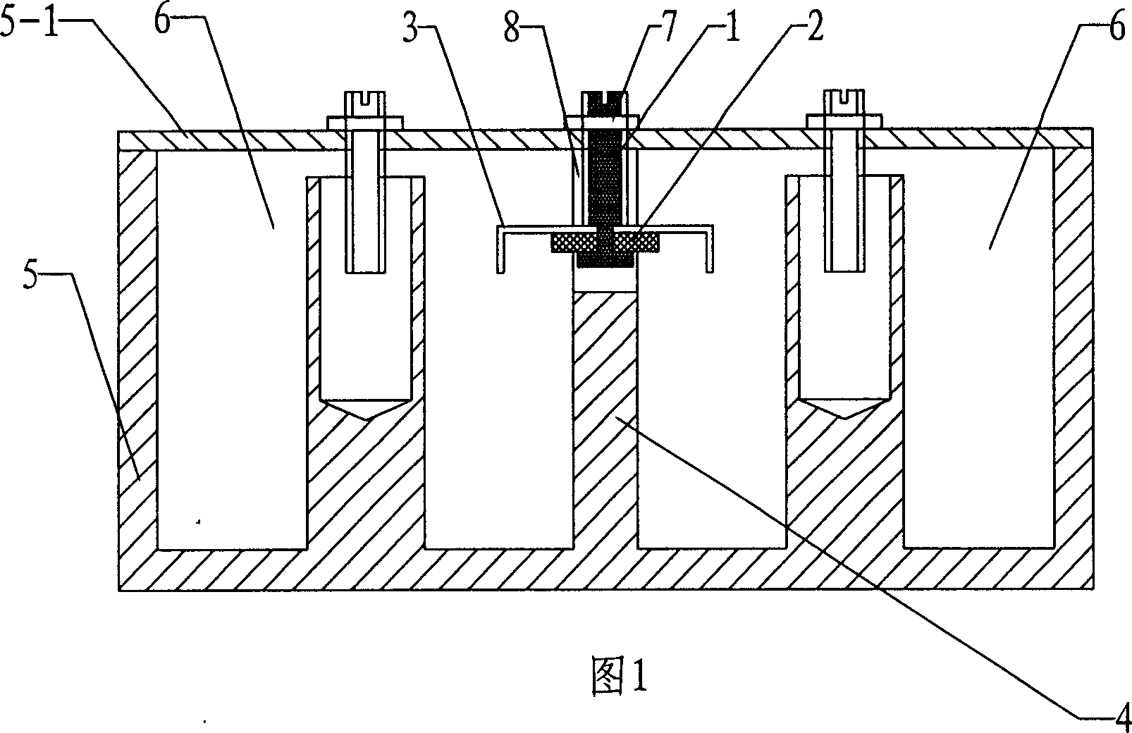
[0021] The present invention will be further described below in conjunction with accompanying drawing:

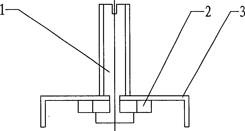
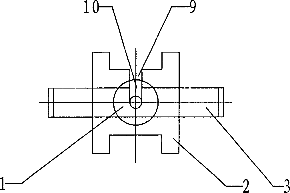
[0022] As shown in the figure, this cavity filter with an adjustable capacitive coupling structure includes a housing 5, and a resonant cavity 6 is opened in the housing 5, and between two non-adjacent coaxial resonant cavities 6 that require capacitive coupling A slot 8 is opened on the partition wall 4 between them, and an adjustable capacitive coupling assembly is arranged in the slot 8, and the adjustable capacitive coupling assembly includes a dielectric screw 1 and a metal sheet 3; the dielectric screw 1 is made of a dielectric material, There is a screw pattern on the upper end, and a thinner cylinder is connected between the bottom and the upper end screw pattern. The upper end of the medium screw 1 is fixed on the cover plate 5-1 through the screw female gasket assembly 7, the lower end of which is located in the slot 8, the metal sheet 3 is fixed on the lower end ...


PUM


Abstract

The filter includes case body. Resonant cavity is built inside the case body. A slotopening is made on the dividing wall between not adjacent concentric resonators needed capacitance to be coupled. A tunable capacitance coupling module is setup in the slotopening. The module includes medium screw, metal piece. Through subassembly of nut and gasket unit, the upper end of the medium screw is fixed on the cover board; and the lower end of the medium screw is on the slotopening. A sheet metal is fixed on lower end of the medium screw. Being extended out of the dividing wall, the sheet metal is folded down. Useful effects of the invention are: (1) since the structure is movable up and down, thus, range of tunable capacitance coupling strength of not adjacent cavities is increased; (2) lowering tuning difficulties and shortening tuning time; (3) avoiding abrasion of screw between cover board and cavity caused by opening cover board for many times; (4) raising performance of insertion loss.

Description

technical field [0001] The invention relates to a radio frequency and cavity filter in the field of wireless communication, in particular to a cavity filter with an adjustable capacitive coupling structure which can conveniently adjust the capacitive coupling strength of non-adjacent cavities in a large range. Background technique [0002] In mobile communication cavity filters, non-adjacent cavity capacitive coupling design is a common method. It can effectively improve the selectivity outside the filter band. There are many non-adjacent cavity capacitive coupling structures. But it is very difficult to adjust the strength of most capacitive couplings. Common adjustment methods are: 1. Open the filter cover to adjust, which is time-consuming and labor-intensive. 2. Each capacitive coupling corresponds to opening two holes on the cover plate for adjustment. After adjustment, stick a metal tape adhesive patch, but the adjustment range is small. Contents of the invention ...

Claims


Application Information

Patent Timeline
Patent Type & Authority Applications(China)
IPC IPC(8): H01P1/20H01P5/02H01P7/04
Inventor 谢瑞华许佳王国峰
Owner SUNWAVE COMM
Why Eureka
Try Eureka