Micro-roughened electrodeposited copper foil and copper clad laminate using the same

a technology of copper foil and micro-roughened electrodeposited copper foil, which is applied in the direction of insulating substrate metal adhesion improvement, transportation and packaging, chemistry apparatus and processes, etc., can solve the problems of reducing the peel strength between the copper foil and the substrate, and achieve good bonding strength, reduce the effect of signal transmission loss and reduce the bonding strength

Active Publication Date: 2020-05-07
CO TECH DEV CORP
View PDF0 Cites 0 Cited by
  • Summary
  • Abstract
  • Description
  • Claims
  • Application Information

AI Technical Summary

Benefits of technology

[0022]One of the advantages of the present disclosure is that the micro-rough surface of the micro-roughened electrodeposited copper foil has a multiplication value of an arithmetic mean height (Sa) and a vertex density (Spd) and an arithmetic mean undulation (Wa), which fall with respective predetermined ranges, such that the signal transmission loss can be significantly reduced without reducing the bonding strength relative to a substrate. That is to say, it can provide a balance of good bonding strength and good insertion loss performance.

Problems solved by technology

However, the decrease of the surface roughness may reduce the peel strength between the copper foil and the substrate.
Therefore, how the peel strength can be maintained at the industry level and provide good insertion loss performance has become a problem to be solved in the related field.

Method used


Image

  • Micro-roughened electrodeposited copper foil and copper clad laminate using the same
  • Micro-roughened electrodeposited copper foil and copper clad laminate using the same
  • Micro-roughened electrodeposited copper foil and copper clad laminate using the same

Examples


example 1

[0053]Reference is made to FIG. 4 along with FIG. 5, a continuous-type electrodepositing apparatus 3 is shown, which can be used to form a micro-rough surface 10 of a micro-roughened electrodeposited copper foil 1. The continuous-type electrodepositing apparatus 3 includes a feeding roll 31, a receiving roll 32, a plurality of electrolyzing tanks 33 (i.e., first to sixth electrolyzing tanks) arranged between the feeding roll 31 and the receiving roll 32, a plurality of electrolyzing roll assemblies 34 respectively arranged above the electrolyzing tanks 33, and a plurality of auxiliary roll assemblies 35 respectively arranged in the electrolyzing tanks 33. Each of the electrolyzing tanks 33 has a pair of electrodes 331 (e.g., platinum electrodes) arranged therein. Each of the electrolyzing roll assemblies 34 includes two electrolyzing rolls 341. Each of the auxiliary roll assemblies 35 includes two auxiliary rolls 351. The pair of platinum electrodes 231 in each of the electrolyzing ...

examples 2 and 3

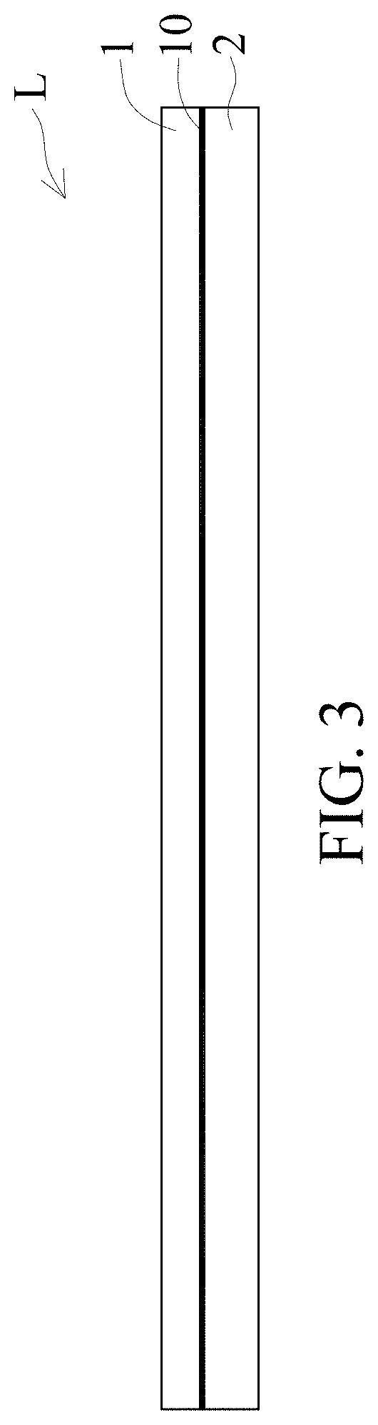
[0058]The raw foil, the electrodepositing apparatus and the composition of the copper-containing electrodeposition solutions are the same as in Example 1. The electrodepositing conditions are shown in Table 1 and the production speed is 10 m / min. One of the micro-roughened electrolysis copper foils 1 of Examples 2 and 3 are used for measurements of Sa and Spd values. Two of the micro-roughened electrolysis copper foils 1 of Examples 2 and 3 are respectively adhered to a substrate 2 that is made of a low-loss prepreg (product name “S7439G”), so as to form two copper clad laminates L. The copper clad laminates L are measured in the same ways as in Example 1, and the results are shown in Table 2.


PUM

PropertyMeasurementUnit
surface roughness Rzaaaaaaaaaa
dissipation factoraaaaaaaaaa
dielectric constantaaaaaaaaaa

Abstract

The present disclosure provides a micro-rough electrolytic copper foil and a copper clad laminate. The electrolytic copper foil has a micro-rough surface formed with mountain-shaped structures and recessed structures. A multiplication value of an arithmetic mean height (Sa) and a vertex density (Spd) of the mountain-shaped structures measured according to ISO 25178 is between 150000 μm/mm2 and 400000 μm/mm2. An arithmetic mean undulation (Wa) of the mountain-shaped structures measured according to JIS B0601:2001 is between 0.06 μm and 1.5 μm. Therefore, the electrolytic copper foil with good binding strength and electrical properties can be obtained.

Description

CROSS-REFERENCE TO RELATED PATENT APPLICATION[0001]This application claims the benefit of priority to Taiwan Patent Application No. 107139174, filed on Nov. 5, 2018. The entire content of the above identified application is incorporated herein by reference.[0002]Some references, which may include patents, patent applications and various publications, may be cited and discussed in the description of this disclosure. The citation and / or discussion of such references is provided merely to clarify the description of the present disclosure and is not an admission that any such reference is “prior art” to the disclosure described herein. All references cited and discussed in this specification are incorporated herein by reference in their entireties and to the same extent as if each reference was individually incorporated by reference.FIELD OF THE DISCLOSURE[0003]The present disclosure relates to an electrodeposited copper foil and its applications, and more particularly to a micro-roughe...

Claims


Application Information

Patent Timeline
Patent Type & Authority Applications(United States)
IPC IPC(8): C25D1/04H05K3/02H05K3/38C25D3/38B32B15/20B32B15/08
CPCH05K3/022B32B15/08B32B15/20H05K3/382C25D1/04C25D3/38B32B15/14B32B3/30B32B2260/021B32B2260/046B32B2262/101B32B15/12H05K1/0242H05K3/384Y10T428/12431
Inventor SUNG, YUN-HSING
Owner CO TECH DEV CORP
Why Eureka
Try Eureka