Dual Mode Dielectric Filter

A dielectric filter and resonant cavity technology, applied in the field of communication, can solve the problems of large insertion loss, small quality factor Q value, and inability to connect the antenna vibrator vertically, and achieves the advantages of small insertion loss, large Q value and good insertion loss performance. Effect

Active Publication Date: 2022-07-05
PIVOTONE COMM TECH
View PDF4 Cites 0 Cited by
  • Summary
  • Abstract
  • Description
  • Claims
  • Application Information

AI Technical Summary

Problems solved by technology

Such a dielectric filter has the following disadvantages: 1) The quality factor Q value is small, and the insertion loss is large; 2) The input and output ends are on the back of the dielectric filter, and cannot be connected vertically to the antenna oscillator

Method used


Image

  • Dual Mode Dielectric Filter
  • Dual Mode Dielectric Filter
  • Dual Mode Dielectric Filter

Examples


Embodiment Construction

[0031] In order to make the objectives, technical solutions and advantages of the embodiments of the present invention clearer, the embodiments of the present invention will be further described in detail below with reference to the accompanying drawings.

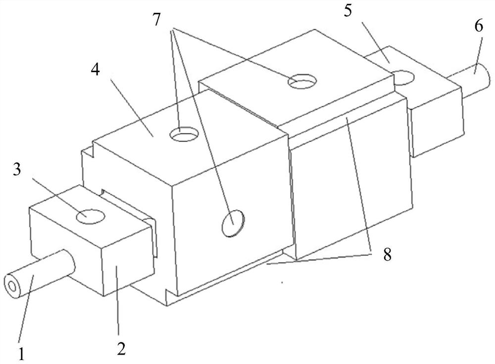
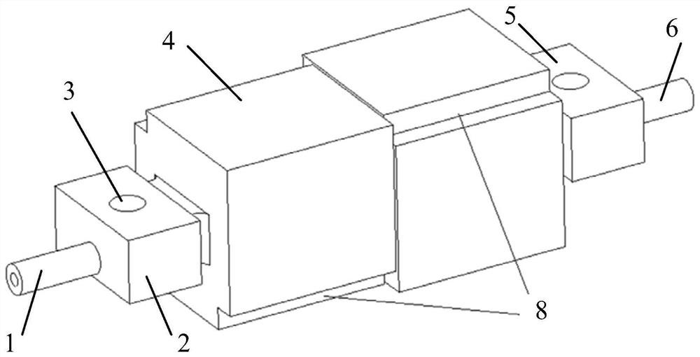
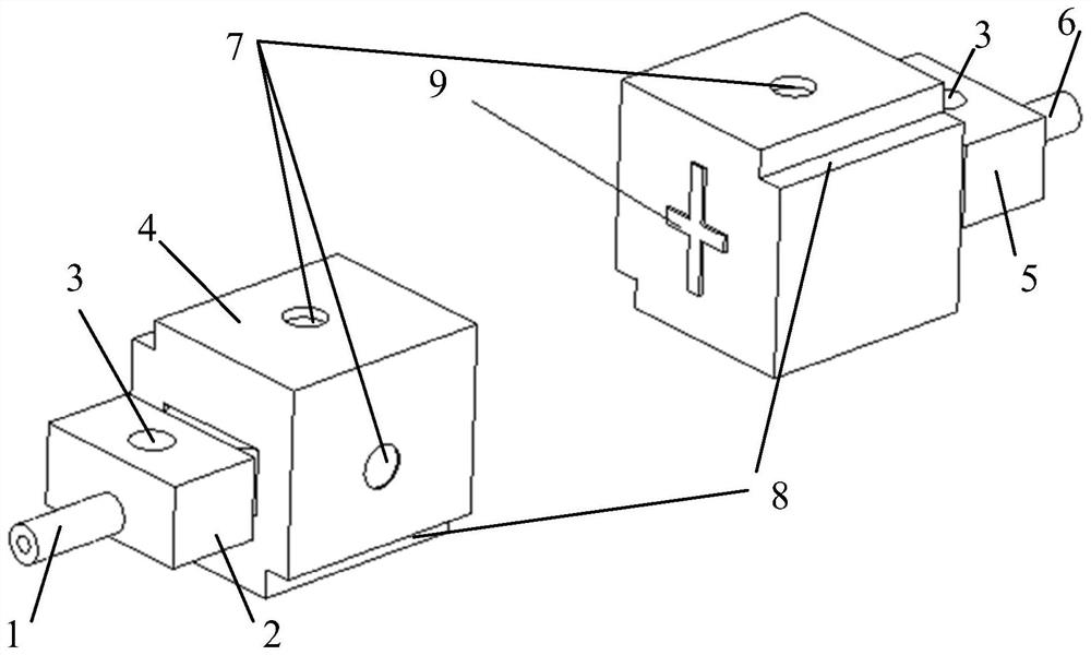
[0032] Please refer to figure 1 , which shows a dual-mode dielectric filter provided by an embodiment of the present invention. The dual-mode dielectric filter includes: an input end 1 , a plurality of resonant cavities, and an output end 6 connected in sequence. The input end 1 and the output end 6 are arranged along the axis direction of the dual-mode dielectric filter, so that the dual-mode dielectric filter and the antenna element can be integrated in the vertical direction.

[0033] The first and last resonant cavities in the plurality of resonant cavities are single-mode resonant cavities, and the remaining resonant cavities are dual-mode resonant cavities 4 . figure 1 The first single-mode resonant cavity 2 and the ...


PUM


Abstract

The invention discloses a dual-mode dielectric filter, which belongs to the technical field of communication. The dual-mode dielectric filter includes: an input end, a plurality of resonant cavities and an output end connected in sequence; the first and last resonant cavities in the plurality of resonant cavities are single-mode resonant cavities, and the remaining resonant cavities are dual-mode A resonant cavity; the dual-mode resonant cavity has a cube structure, and the dual-mode resonance cavity realizes dual-mode resonance through the orthogonal degenerate modes of the cube structure. The input end and the output end of the present invention are at both ends of the dual-mode dielectric filter, which facilitates the vertical connection of the dual-mode dielectric filter and the antenna element. In addition, the first and the last resonant cavity in the plurality of resonant cavities are single-mode resonant cavities, and the remaining resonant cavities are dual-mode resonant cavities, and the dual-mode resonant cavities have a cube structure, and the dual-mode resonator cavities pass through the orthogonality of the cube structure. The degenerate mode of , realizes dual-mode resonance, therefore, the dual-mode dielectric filter can be made less loaded, larger in Q value, and smaller in insertion loss.

Description

technical field [0001] Embodiments of the present invention relate to the field of communication technologies, and in particular, to a dual-mode dielectric filter. Background technique [0002] Sub 6GHz in 5G (5th Generation) communication adopts MIMO (Multi-Input Multi-Output) technology, which requires a large number of filters to be integrated inside the antenna. Therefore, the loss of filters, out-of-band suppression, power Capacity, volume, weight, etc. have higher requirements. If a traditional metal filter is selected, the volume and weight of the traditional metal filter are too large to be integrated inside the antenna. If a small dielectric waveguide filter is selected, the above requirements can be met. Therefore, the dielectric filter has become a hot research topic at present. [0003] The dielectric filter in the related art includes a plurality of resonant cavities, and each resonant cavity adopts the working mode of the main mode, so that one resonant cavit...

Claims


Application Information

Patent Timeline
Patent Type & Authority Patents(China)
IPC IPC(8): H01P1/212H01P1/20
CPCH01P1/212H01P1/2002Y02D30/70
Inventor 江顺喜梁国春殷实项显杜锦杰
Owner PIVOTONE COMM TECH
Why Eureka
Try Eureka