Nozzle device and hygienic washing device with same

A nozzle device and sanitary washing technology, which is applied to sanitary equipment for toilets, water supply devices, buildings, etc., can solve the problems of reduced washing water flow rate, insufficient washing, low washing water density, etc., and achieve pressure loss. Small, miniaturized sanitary cleaning device, easy cleaning effect

Inactive Publication Date: 2006-05-24
PANASONIC CORP
View PDF3 Cites 10 Cited by
  • Summary
  • Abstract
  • Description
  • Claims
  • Application Information

AI Technical Summary

Problems solved by technology

[0013] However, in the above-mentioned conventional nozzle device, the washing water sprayed from the drain hole through the swirl imparting chamber from the axis-directed pipe receives a large flow resistance in the swirl imparting chamber, resulting in a pressure loss.
Therefore, the flow velocity of the washing water sprayed from the drain h

Method used


Image

  • Nozzle device and hygienic washing device with same
  • Nozzle device and hygienic washing device with same
  • Nozzle device and hygienic washing device with same

Examples


Embodiment 1

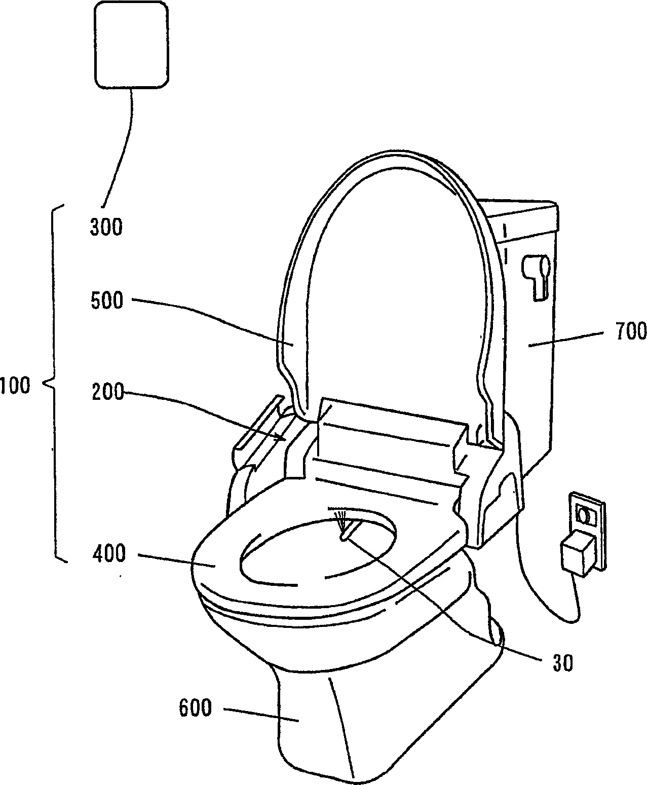
[0172] figure 1 It is a perspective view showing a state in which the sanitary washing device according to Embodiment 1 of the present invention is attached to a toilet.

[0173] Such as figure 1 As shown, the sanitary washing device 100 is installed on a toilet 600 . The water tank 700 is connected to a water pipe to supply flush water into the toilet 600 .

[0174] The sanitary washing device 100 is composed of a main body 200 , a remote control device 300 , a toilet seat 400 and a cover 500 .

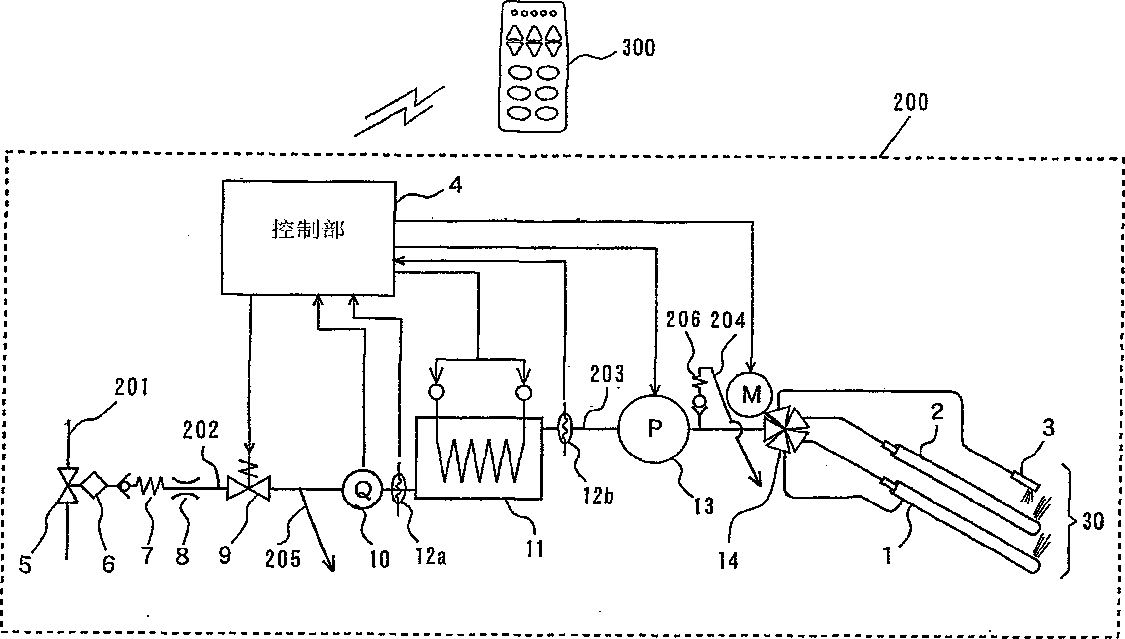
[0175] The toilet seat part 400 and the cover part 500 are attached to the main body part 200 openably and closably. Furthermore, a washing water supply mechanism including a nozzle unit 30 is provided on the main body unit 200, and a control unit is incorporated therein. The control unit of the main body unit 200 controls the washing water supply mechanism based on a signal transmitted from the remote control device 300 as will be described later. Moreover, the control part of ...

Embodiment 2

[0296] The difference between the structure of the piston part of the buttock nozzle 1 of the second embodiment and the structure of the piston part 20a of the buttock nozzle 1 of the first embodiment, and their effects will be described below with reference to the drawings.

[0297] Figure 22 (a) is a perspective view showing the piston part of the rear nozzle, Figure 22 (b) is an exploded perspective view showing the washing water supply part of the piston part. Figure 23 It is an exploded perspective view showing the piston part of the rear nozzle, Figure 24 (a) is a side view of the piston part 20a, Figure 24 (b) is a top view of the piston part 20a.

[0298] Such as Figure 22 As shown in (a), the piston part 20 a includes a nozzle cover 401 and a washing water supply part 420 . exist Figure 22 In (a), the nozzle cover 401 is shown by the dashed-dotted line. The washing water supply part 420 includes a second channel pipe 402c, a first channel pipe 403c, and ...

Embodiment 3

[0350] The difference between the structure of the main body portion of the sanitary washing device of Embodiment 3 and the structure of the main body portion 200 of the sanitary washing device of Embodiment 1 and their effects will be described below with reference to the drawings.

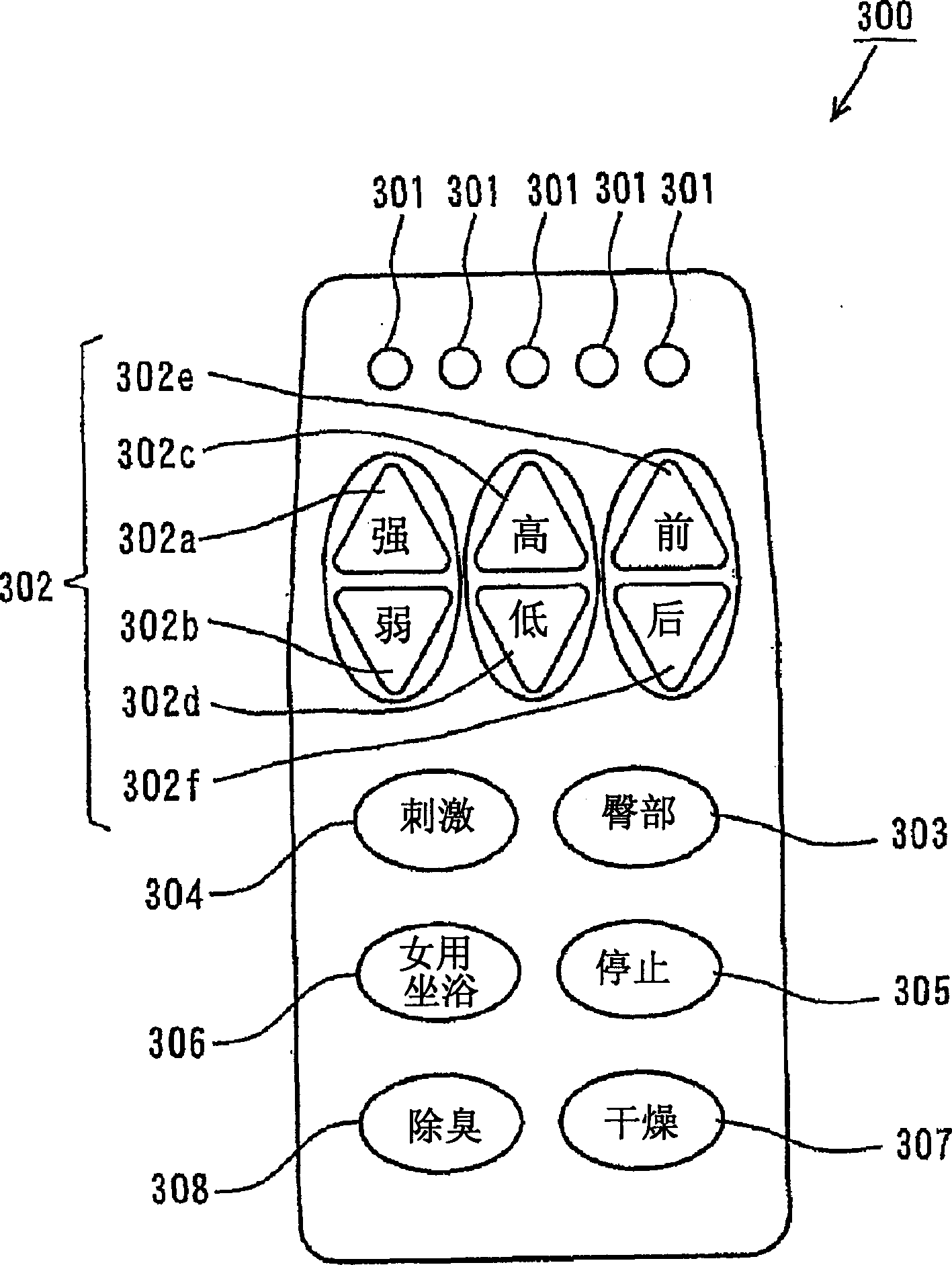
[0351] Figure 29 yes figure 1 A schematic diagram of another example of the remote operating device 300.

[0352] Such as Figure 29 As shown, the remote control device 300 is the same as that of Embodiment 1 figure 1 The difference of the remote control device 300 is that it also has a nozzle cleaning switch 309 and a nozzle high temperature cleaning switch 310 .

[0353] When the nozzle cleaning switch 309 is pressed, the nozzle part 30 is cleaned with washing water, and when the nozzle high temperature cleaning switch 310 is pressed, the nozzle part 30 is washed with the washing water heated to a high temperature. Details of the cleaning operation of the nozzle unit 30 performed by pressi...


PUM

PropertyMeasurementUnit
Diameteraaaaaaaaaa

Abstract

Since the inner diameter of the constriction portion decreases continuously toward the cylindrical swirl chamber, the flow velocity of the washing water flowing through the constriction portion continuously increases. Since the inner diameter of the constriction portion is continuously reduced toward the spray hole, the flow velocity of the washing water flowing through the constriction portion is continuously increased. The washing water supplied to one channel of the second channel tube flows through the first channel tube and is supplied to the confluence of the channel channels. The washing water supplied to the other channel of the second channel tube flows through the space between the first channel tube and the nozzle cover, and then is supplied to the channel confluence part. The washing water sprayed from the nozzle washing hole spirally rotates along the outer peripheral surface of the piston in the space between the inner wall of the nozzle washing cylinder and the outer peripheral surface of the piston, and flows out from the front end opening of the nozzle washing cylinder. A position fixing piece having a curved surface shape along the inner surface of the front end portion of the nozzle cover is formed at the front end portion of the flow path confluence portion. Dispersed swirling streams are ejected alternately with straight streams during movement of the rear nozzle from the front position to the rear position.

Description

(1) Technical field [0001] The present invention relates to a sanitary washing device for washing part of the human body. (2) Background technology [0002] In a sanitary washing device for washing a part of a human body, washing water is sprayed from a nozzle protruding from a storage position to a washing position of the nozzle device to perform washing. [0003] In such a nozzle device, during the washing operation, the tip of the nozzle comes close to a part of the human body and sprays washing water. In this case, dirt may adhere to the nozzle during cleaning, so various functions for cleaning the nozzle have been proposed. [0004] As a function of cleaning the nozzle, for example, cleaning by a nozzle cleaning nozzle is mentioned (for example, refer to Japanese Patent Application Laid-Open No. 11-193567). In this case, before or after the operation of washing the human body part, the washing water flows into the nozzle to clean the dirt adhering to the nozzle itself...

Claims


Application Information

Patent Timeline
IPC IPC(8): E03D9/08
Inventor 古闲良一有川富夫円口至河本恭宏
Owner PANASONIC CORP
Why Eureka
Try Eureka