Method for mounting rotor blades and rotor blade for a wind turbine

一种转子叶片、转子的技术,应用在安装转子叶片及风轮机的转子叶片领域,能够解决起重机变大等问题,达到简单控制和影响的效果

Inactive Publication Date: 2006-05-24
阿洛伊斯沃本
View PDF0 Cites 9 Cited by
  • Summary
  • Abstract
  • Description
  • Claims
  • Application Information

AI Technical Summary

Problems solved by technology

Therefore, the required cranes are also larger

Method used


Image

  • Method for mounting rotor blades and rotor blade for a wind turbine
  • Method for mounting rotor blades and rotor blade for a wind turbine
  • Method for mounting rotor blades and rotor blade for a wind turbine

Examples


Embodiment Construction

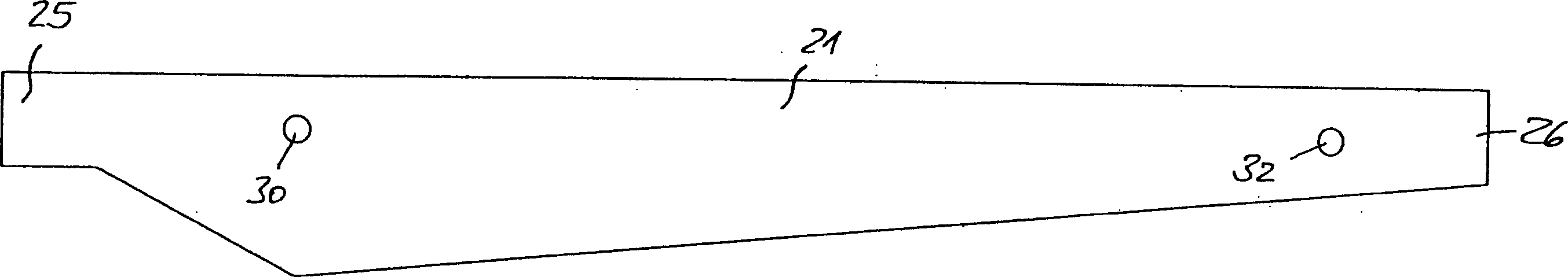
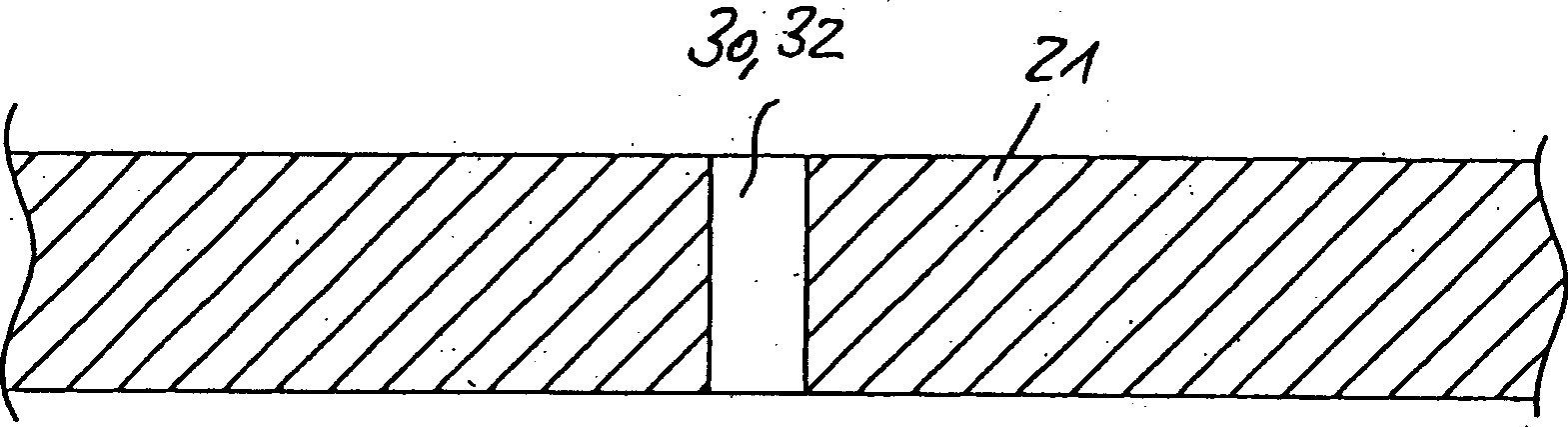
[0031] figure 1 The plan view in is a simplified view of the rotor blade 21 . The rotor blade 21 has two through holes 30 , 32 in the longitudinal direction between the rotor blade root 25 and the rotor blade tip 26 . The through-hole 32 is arranged in the region of the rotor blade tip 26 , while the through-hole 30 is arranged in the region close to the rotor blade root. In this case, these positions are determined in such a way that a safe and reliable handling of the rotor blade must be ensured when the rotor blade is mounted on the rotor hub of the wind power plant. When determining the positions of the holes 30 , 32 , the connection means with respect to the load-bearing structure of the rotor blade 21 are also taken into account.

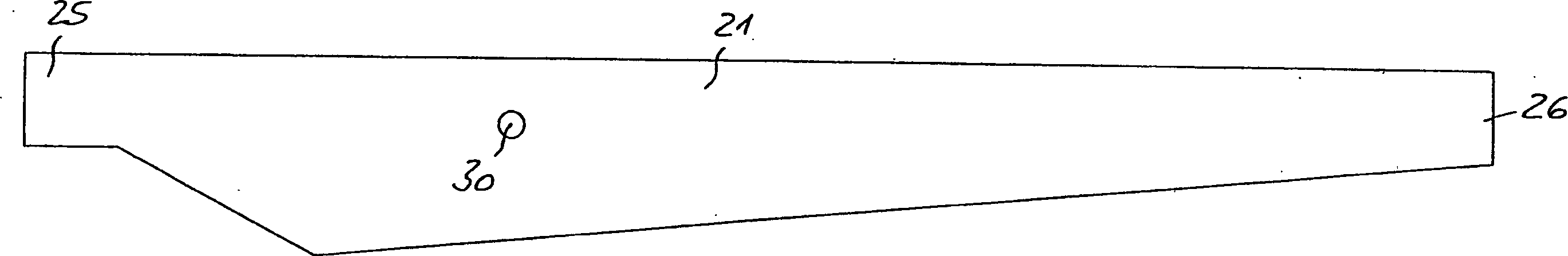
[0032] figure 2 A further embodiment of the rotor blade 21 is shown, which has only one through-opening 30 . This single through-hole 30 is suitably arranged at the center of gravity of the rotor blade so that the blade can be safely mani...


PUM


Abstract

The invention relates to a method of mounting a rotor blade to a rotor hub connected to a nacelle of a wind turbine. Said method comprises the steps of: rotating said rotor hub to a predetermined first position; mounting a rotor blade (21); rotating said rotor hub by said first rotor blade (21) turning to a predetermined second position; and installing a second rotor blade (22); wherein the rotation of the rotor hub is achieved along the direction of gravity of the installed first rotor blade (21) of. Thus, a crane sufficient to mount the rotor hub itself and the nacelle can also be used to mount rotor blades to a wind turbine with a relatively tall hub. The invention also relates to a rotor blade to be mounted on a wind power installation, said rotor blade having at least one hole.

Description

technical field [0001] The invention relates to a method of mounting a rotor blade to a rotor hub connected to a pod of a wind power installation, and to a rotor blade for a wind power installation. Background technique [0002] Rotor blades for wind power installations are well known. As the size of wind power plants increases and the output power increases, so does the size of the rotor blades and their own weight. Therefore, it is necessary to install the components using a crane, which can transport a load with increased dead weight to a higher place. Therefore, the required cranes also become larger. Contents of the invention [0003] The object of the invention is to simplify the installation of the rotor blade and to increase the maneuverability of the rotor blade. [0004] The object of the invention is achieved by a method of mounting a rotor blade as claimed in claim 1 and by a rotor blade as claimed in claim 6 . [0005] Mounting of rotor blades to a rotor h...

Claims


Application Information

Patent Timeline
Patent Type & Authority Applications(China)
IPC IPC(8): F03D1/00F03D1/06
CPCF03D1/0658F05B2230/60F03D13/10Y10T29/49329Y10T29/4984Y10T29/49327Y10T29/49316Y02E10/72Y02E10/728Y02P70/50
Inventor 艾劳埃斯·乌本
Owner 阿洛伊斯沃本
Why Eureka
Try Eureka