Cooling plate integrated module and battery module
A cooling plate and component technology, applied in the field of heat exchange cooling, can solve the problems of high cost, high power consumption, low efficiency, etc., and achieve the effects of simple structure, improved heat exchange efficiency, and high heat exchange efficiency
- Summary
- Abstract
- Description
- Claims
- Application Information
AI Technical Summary
Problems solved by technology
Method used
Image
Examples
Embodiment 1
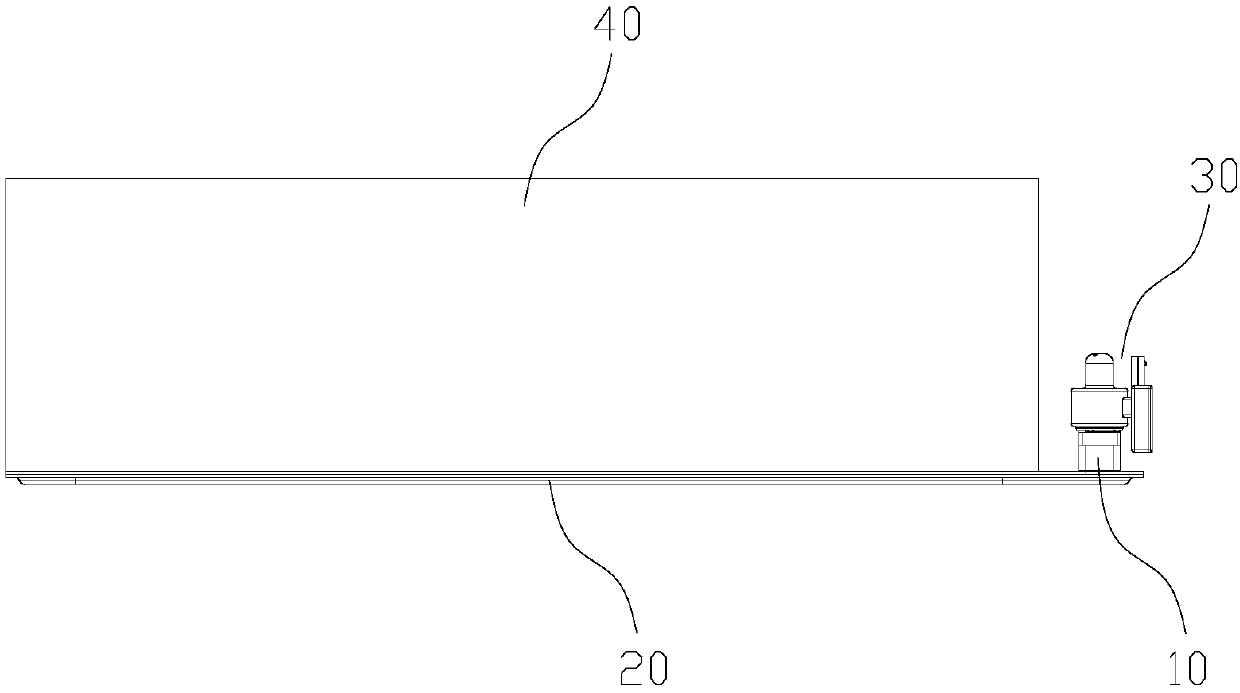
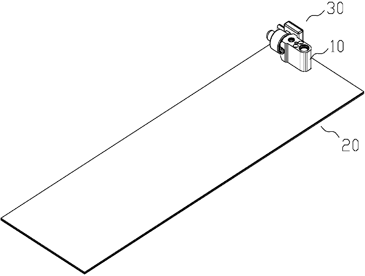
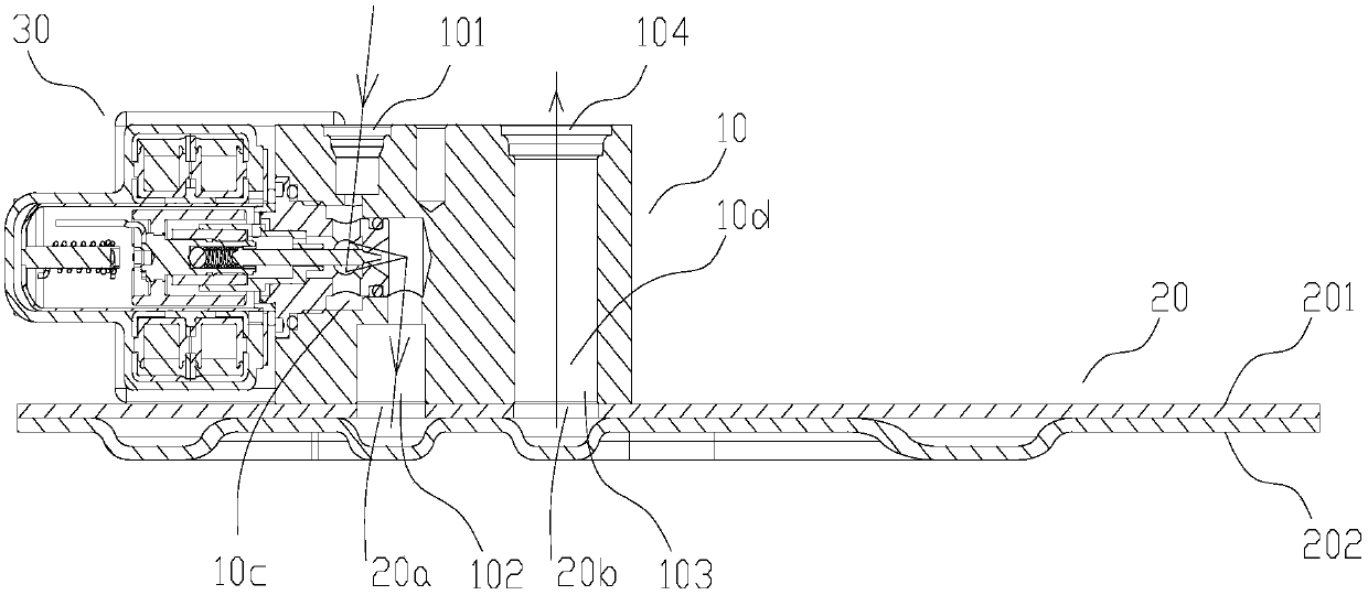
[0074] Please refer to Figure 1-6 , figure 1 It is a schematic structural diagram of the first embodiment of the battery assembly provided by the present invention; figure 2 for figure 1 Schematic diagram of the structure of the cooling plate integrated assembly in the battery assembly; image 3 for figure 2 Cutaway view of the cooling plate integrated assembly; Figure 4 for image 3 The schematic diagram of the structure after removing the spool assembly 30; Figure 5 for figure 2 Schematic diagram of the structure of the cooling plate bottom plate 201 in the cooling plate integrated assembly; Figure 6 for figure 2 Schematic diagram of the structure of the cooling plate channel plate 202 in the cooling plate integrated assembly.
[0075] In this embodiment, the battery assembly includes a battery module 40 and a cooling plate integration assembly, including a cooling plate 20, a valve core assembly 30, and a connecting block 10. The valve assembly formed by c...
Embodiment 2
[0100] Please refer to Figure 11-16 , Figure 11 It is a structural cross-sectional view of the second embodiment of the cooling plate integrated assembly provided by the present invention; Figure 12 for Figure 11 The schematic diagram of the structure after removing the spool assembly 30; Figure 13 for Figure 12 Schematic diagram of the structure of the connecting block 10 in the cooling plate integrated assembly; Figure 14 for Figure 12 top view of Figure 15 for Figure 13 bottom view of Figure 16 for Figure 13 A cross-sectional view of the connecting block 10.
[0101] The structure of the connection block 10 in this embodiment is different from that of the embodiment 1, and the other structures are the same, and the connection and conduction methods between the connection block 10 and the cooling plate 20 are also the same, so details will not be repeated.
[0102] In the second embodiment, the orifice of the mounting hole 105 for installing the spool c...
Embodiment 3
[0109] Please refer to Figure 17-22 , Figure 17 It is a structural cross-sectional view of the third embodiment of the cooling plate integrated assembly provided by the present invention; Figure 18 for Figure 17 The schematic diagram of the structure after removing the spool assembly 30; Figure 19 for Figure 18 Schematic diagram of the structure of the connecting block 10 in the cooling plate integrated assembly; Figure 20 for Figure 19 top view of Figure 21 for Figure 19 bottom view of Figure 22 for Figure 19 A cross-sectional view of the connecting block 10.
[0110] The structure is basically the same as that of Embodiment 2. The orifice of the mounting hole 105 in Embodiment 3 is also set on the outer end surface of the connecting block 10 with the first port 101 of the connecting block and the fourth port 104 of the connecting block, and the threaded hole 108 is located on the connecting block. The side end surface of the block 10 , and a drainage fl...
PUM
| Property | Measurement | Unit |
|---|---|---|
| Thickness | aaaaa | aaaaa |
Abstract
Description
Claims
Application Information
 - R&D
- Intellectual Property
- Life Sciences
- Materials
- Tech Scout
- Unparalleled Data Quality
- Higher Quality Content
- 60% Fewer Hallucinations
Browse by: Latest US Patents, China's latest patents, Technical Efficacy Thesaurus, Application Domain, Technology Topic, Popular Technical Reports.
© 2025 PatSnap. All rights reserved.Legal|Privacy policy|Modern Slavery Act Transparency Statement|Sitemap|About US| Contact US: help@patsnap.com


