Unit assembly type equally divided displacement comb tooth bridge expansion device

A telescopic device and assembled technology, which is applied in bridges, bridge parts, bridge construction, etc., can solve problems such as seismic isolation defects, limited tooth side clearance, and easy fatigue of the device, so as to achieve simple and convenient construction and assembly process, and ensure accuracy and strength , Improve the effect of construction efficiency

Pending Publication Date: 2019-11-15
WUHAN JIUNAI EXPANSION ENG CO LTD
View PDF0 Cites 3 Cited by
  • Summary
  • Abstract
  • Description
  • Claims
  • Application Information

AI Technical Summary

Problems solved by technology

[0004] 1. The intersecting telescopic teeth of the large-displacement comb-shaped bridge telescopic device have limited tooth side clearance, and there is a mechanical contradiction of mutual interference when the large-displacement bridge rotates horizontally;
[0005] 2. The intersecting telescopic teeth of the large-displacement bridge telescopic device are too long, so there is a traffic safety problem of warped teeth when rotating vertically;
[0006] 3. In the existing comb-shaped expansion joints, the left and right combs are installed alternately on the left and right bridges. When the shrinkage is large in winter, the conca

Method used


Image

  • Unit assembly type equally divided displacement comb tooth bridge expansion device
  • Unit assembly type equally divided displacement comb tooth bridge expansion device
  • Unit assembly type equally divided displacement comb tooth bridge expansion device

Examples


Embodiment Construction

[0045] The embodiments of the present invention will be further described below in conjunction with the accompanying drawings. Examples of the embodiments are shown in the accompanying drawings, wherein the same or similar symbols throughout represent the same or similar elements or elements with the same or similar functions. The embodiments described below by referring to the accompanying drawings are exemplary and are intended to explain the present invention, but should not be construed as limiting the present invention. Any modifications, equivalent replacements or Improvements, etc., should be included within the scope of the claims of the present invention, and those not described in detail in this technical solution are all known technologies.

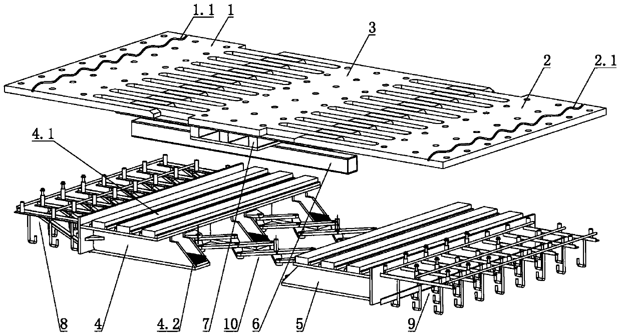
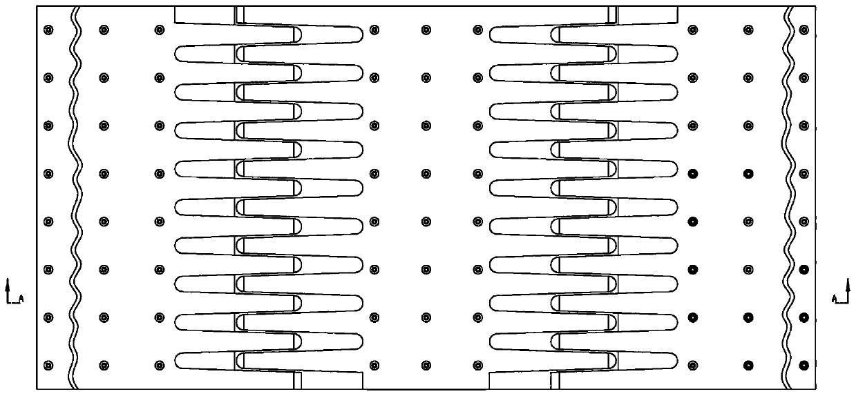
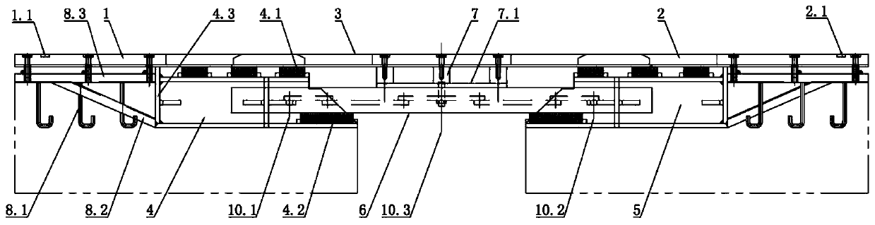
[0046] Such as Figure 1-8 As shown, it is a unit-assembled equal-displacement comb-tooth bridge expansion device of the present invention, which is a comb-tooth-shaped expansion device for large-span bridges (expansion amount ...


PUM


Abstract

The invention discloses a unit assembly type equally divided displacement comb tooth bridge expansion device which is mounted in a bridge with the expansion amount greater than or equal to 1000 mm. The unit assembly type equally divided displacement comb tooth bridge expansion device comprises a left displacement box, a right displacement box, hinges, displacement box girders, a cross beam, a leftcomb tooth plate, a middle comb tooth plate, a right comb tooth plate and two groups of hinges, wherein the left displacement box, the right displacement box, the hinges, the displacement box girders, the cross beam, the left comb tooth plate, the middle comb tooth plate and the right comb tooth plate are fixedly connected to beam ends; the left comb tooth plate and the right comb tooth plate arerespectively and fixedly connected with the left displacement box girder and the right displacement box girder through high-strength bolts; the displacement box girders are respectively and fixedly connected with the left beam end and the right beam end; the middle comb tooth plate is fixedly connected with the cross beam; the cross beam is arranged on the displacement box girders; and at least one earthquake-reduction and seismic-isolation support is arranged below each of the left comb tooth plate, the middle comb tooth plate and the right comb tooth plate; two ends of the hinges are respectively hinged to the left displacement box and the right displacement box; the middles of the hinges are fixedly connected with the cross beam through hinge pins; sinusoid-shaped anti-sliding groovesare transversely formed in the upper surface of each comb tooth plate; and when the bridge stretches and retracts, the middle comb tooth plate is displaced in an equally divided manner relative to theleft comb tooth plate and the right comb tooth plate. By adopting the device, interference resistance is facilitated, the device is safe and noiseless, and the mounting process is convenient, time-saving and accurate.

Description

technical field [0001] The invention relates to a unit-assembled equidisplacement comb tooth bridge telescopic device, which belongs to the technical field of bridge engineering. Background technique [0002] The bridge expansion device is an important connecting part between the beam end abutments of road and railway bridges. It plays an important role in the expansion and contraction of the bridge end abutments, as well as waterproof, dustproof, shockproof and other performances. Its quality and performance will directly affect the entire abutment. The durability of bridges is an important part of highway and railway bridge construction. Since the bridge telescopic device is installed on the weak part of the abutment bridge deck at the beam end, and has been subjected to various natural environmental erosion effects, there will be multi-directional changes in the process of use, such as cold and hot expansion, longitudinal swing, and lateral swing relative torsion. Positi...

Claims


Application Information

Patent Timeline
IPC IPC(8): E01D19/06
CPCE01D19/065
Inventor 刘力源
Owner WUHAN JIUNAI EXPANSION ENG CO LTD
Why Eureka
Try Eureka