Vibration wave motor and lens barrel

A technology of vibration wave and vibrator, which is applied in the direction of generators/motors, circuits, electrical components, etc., can solve the problem of not fully considering the unitization of driving sources

Inactive Publication Date: 2006-05-31
OLYMPUS CORP
View PDF1 Cites 12 Cited by
  • Summary
  • Abstract
  • Description
  • Claims
  • Application Information

AI Technical Summary

Problems solved by technology

Therefore, there is a problem that the above-mentioned vibrator supported by the above-mentioned leaf spring member is in frictional contact with the above-mentioned ring-shaped relative moving member in an inclined state.
[0005] In addition, the vibration actuator disclosed in the above-mentioned Patent Document 1 does not fully consider the problem of unitization as a drive source.

Method used


Image

  • Vibration wave motor and lens barrel
  • Vibration wave motor and lens barrel
  • Vibration wave motor and lens barrel

Examples


Embodiment Construction

[0079] Embodiments of the present invention will be described below with reference to the drawings.

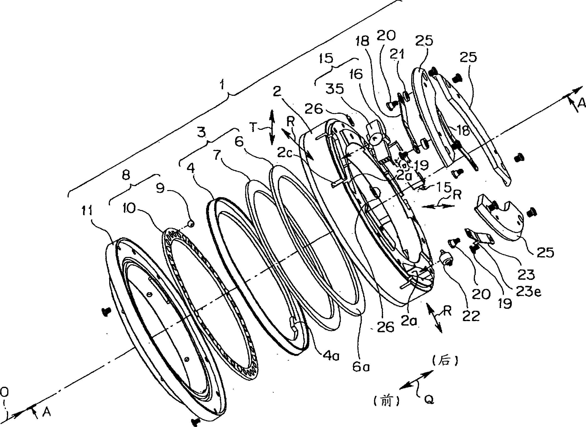
[0080] figure 1 It is an exploded perspective view of the vibration wave motor according to one embodiment of the present invention.

[0081] In the following description, when the vibration wave motor is used on the lens barrel described later, the rotation axis O of the vibration wave motor coincides with the optical axis O of the photographing lens (according to the structure of the above-mentioned lens barrel, approximately coincides). Also, let the direction parallel to the rotation axis O be the Q direction. In the Q direction, the lens side of the lens barrel is defined as the front, and the lens holder side is defined as the rear. In addition, let the radial direction with respect to the rotation axis O be the R direction, and let the tangential direction of the circumference around the rotation axis O be the T direction.

[0082] The vibration wave motor 1 of the p...


PUM


Abstract

The vibration wave motor of the present invention includes: a housing; a rotor; a bearing member; a vibrator as an actuator having a support shaft and a driver; and a leaf spring having a pressing protrusion. The vibrator is held in a state where it is slidable in the opening of the case along the direction of the axis of rotation, and its support shaft is supported and inserted freely to rotate, and the driver is brought into contact with the above-mentioned driving member by the biasing force of the leaf spring. on the rotor. When the vibration wave is excited by the vibrator, the rotor is driven to rotate, the vibrator is held in the housing so as to be movable along the direction of the rotation axis, and the vibrator is pressed by the leaf spring, so that the vibrator abuts against the rotor. The side friction contact surface, so the vibrator can abut against the above-mentioned rotor evenly and perpendicularly to the contact friction surface, and a good driving state of the motor can be obtained.

Description

technical field [0001] The invention relates to a vibration wave motor and a lens barrel assembled with the vibration wave motor. Background technique [0002] Generally, a vibration wave motor used as a driving device is composed of a vibrator (vibrator) having an energy conversion element such as a piezoelectric element, and a contact piece crimped on the vibrator. The kinetic energy generated by the wave and the standing wave is converted into the relative motion of the above-mentioned vibrator and the above-mentioned contact piece. In this case, the output of the vibration wave motor is largely influenced by the friction interface between the vibrator and the contact, and is also influenced by the number of vibrators. For this reason, many ultrasonic motors having crimping mechanisms with various vibrators have been proposed. [0003] A vibration actuator (vibration wave motor) is disclosed in Japanese Patent Laid-Open Publication No. Hei 11-235062. This vibration act...

Claims


Application Information

Patent Timeline
Patent Type & Authority Applications(China)
IPC IPC(8): H02N2/00G02B7/04H02N2/10
CPCG02B7/08H02N2/006H02N2/103H10N30/2023
Inventor 滝泽宏行中前敦酒谷孝次川合澄夫
Owner OLYMPUS CORP
Why Eureka
Try Eureka