Method of adding mass to MEMS structures

A micro-electromechanical sensor and detection mass technology, applied in the field of MEMS devices, can solve the problems of increased weight, increased size, and unpopularity of the detection mass.

Inactive Publication Date: 2006-05-31
FREESCALE SEMICON INC
View PDF1 Cites 16 Cited by
  • Summary
  • Abstract
  • Description
  • Claims
  • Application Information

AI Technical Summary

Problems solved by technology

Consequently, it is difficult to substantially increase the weight of the proof mass without substantially increasing the size of the sensor, a result that is highly unfavorable in view of the current demands in the art for further miniaturization of these devices. of

Method used


Image

  • Method of adding mass to MEMS structures
  • Method of adding mass to MEMS structures
  • Method of adding mass to MEMS structures

Examples


example 1

[0045] This example is used to illustrate the effect of CTE differential stress between the appendage of the proof mass and the base for a proof mass separated from the base by a narrow rod and the appendages are composed of different materials (i.e. aluminum and polysilicon). transfer.

[0046] Repeat the simulation test of comparative example 1, but adopt such as Image 6 Proof masses of the type indicated. The detection mass body 51 is composed of a polysilicon substrate 53 and a square appendage 55 connected thereto. The appendages consist of a layer of polysilicon 59 with a layer 57 of aluminum deposited to a thickness of 3 microns. The side length of the appendages is 100 μm. The appendages are separated from the base body by rods 61 having a width of 3 microns and a length of 2 microns, the main surfaces of the appendages being parallel to those of the base body.

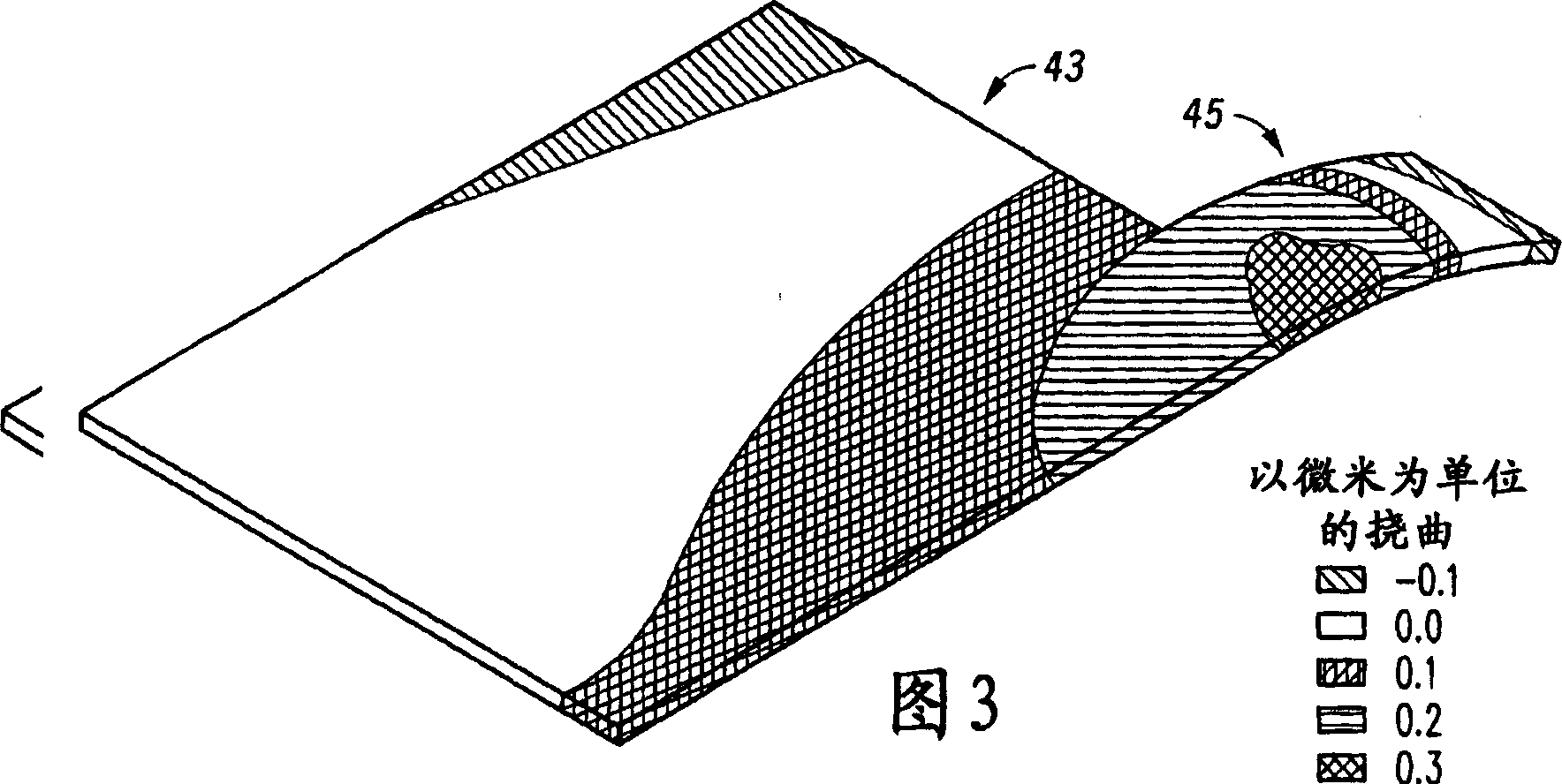
[0047] The calculated stresses during the temperature cycle from 25°C to 125°C are shown graphically i...


PUM


Abstract

The invention provides a detection mass body (11) for MEMS devices. The proof mass comprises a base body (13) comprising semiconductor material, and at least one appendage (15) connected to said base body by a rod (21). The appendage (15) consists of metal (17) or another material which can be provided on the semiconductor material (19). The metal increases the overall mass of the proof mass (11) without increasing the size of the proof mass compared to a similarly sized proof mass made of only semiconductor material. At the same time, connecting the appendages (15) via rods (21) prevents stresses caused by CTE differences in the appendages, which could lead to temperature errors, from being transmitted to the base body.

Description

technical field [0001] The present invention relates generally to MEMS devices and, in particular, to proof masses for MEMS devices. Background technique [0002] Advances in micromachining and other microfabrication techniques and processes have enabled the fabrication of a wide variety of MicroElectroMechanical Sensors (MEMS) and other such devices. These devices include moving rotors, gears (transmissions), switches, accelerometers, miniaturized sensors, actuator systems, and other such structures. [0003] One promising application of MEMS technology is in the field of inertial sensors. Inertial sensors work by sensing the displacement of a proof mass mounted on a compliant suspension. The proof-mass displacement ΔX is related to the mass (m) of the proof-mass, the acceleration (a), and the spring constant (k) of the compliant suspension, as shown in Equation 1: [0004] ΔX=ma / k (equation 1) [0005] The sensitivity of an inertial sensor is limited by the ability of ...

Claims


Application Information

Patent Timeline
Patent Type & Authority Applications(China)
IPC IPC(8): B32B9/00B32B15/04C23F1/00G01P3/00G01P9/04G01P15/08H01L
CPCB81B3/0078B81B2201/025G01P15/08G01P15/0802G01P15/0888G01P2015/0814Y10T428/24917B32B9/00B81B7/02C23F1/00G01P3/00
Inventor 安德鲁·C.·麦克尼尔加里·李加里·J.·奥'·布里恩
Owner FREESCALE SEMICON INC
Why Eureka
Try Eureka