Device for producing special yarn

A kind of yarn manufacturing and special technology, applied in the field of special yarn manufacturing equipment, can solve the problems of not being able to produce yarn, not being able to guarantee reproducibility, etc.

Active Publication Date: 2006-06-07
TOYOTA IND CORP
View PDF2 Cites 5 Cited by
  • Summary
  • Abstract
  • Description
  • Claims
  • Application Information

AI Technical Summary

Problems solved by technology

However, since the above-mentioned data of the slub S are random, it is not possible to produce consistent yarns among full b

Method used


Image

  • Device for producing special yarn
  • Device for producing special yarn
  • Device for producing special yarn

Examples


no. 1 approach

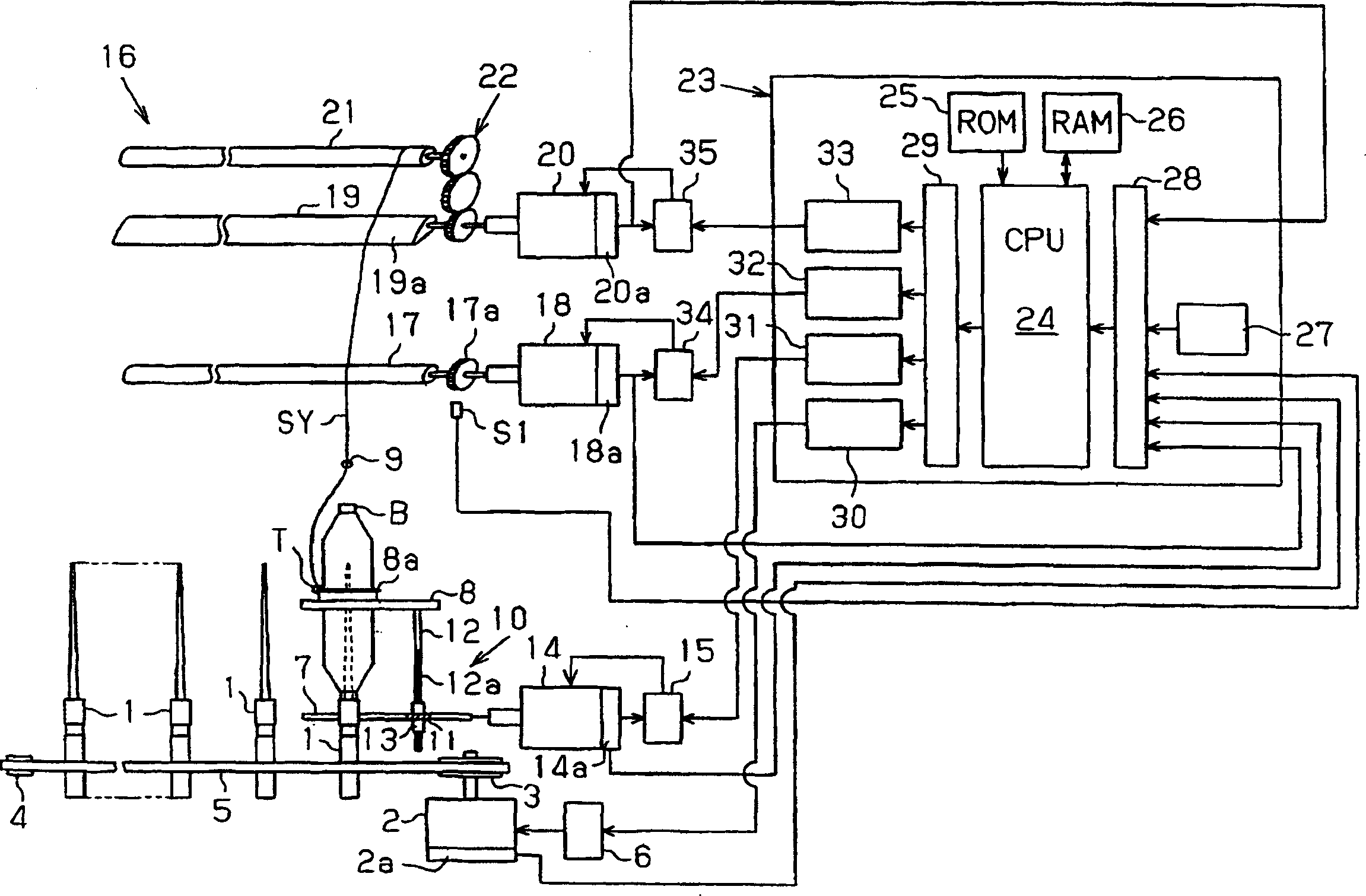
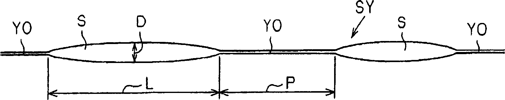
[0012] Below, according to Figure 1 ~ Figure 3 A first embodiment will be described, which embodies the present invention as a special yarn manufacturing device that forms slubs by changing the speed of the front roller. figure 1 It is a structural diagram of the special yarn manufacturing device, and Fig. 2 is a partial schematic diagram of the special yarn.

[0013] The special yarn manufacturing device basically has the same structure as the ring spinning machine. Such as figure 1 As shown, the spindle 1 is driven to rotate by the spindle drive system. The spindle drive system has: a driving pulley 3 driven by a motor 2, a driven pulley 4, and a tangential transmission belt 5 wound between the two pulleys 3,4. The motor 2 is a variable speed motor driven via an inverter 6, and has a rotary encoder 2a. The main shaft 7 is rotatably arranged along the spindle row. Elevating assemblies 10 (only one is shown in the figure) are arranged at predetermined intervals on the mai...

no. 2 approach

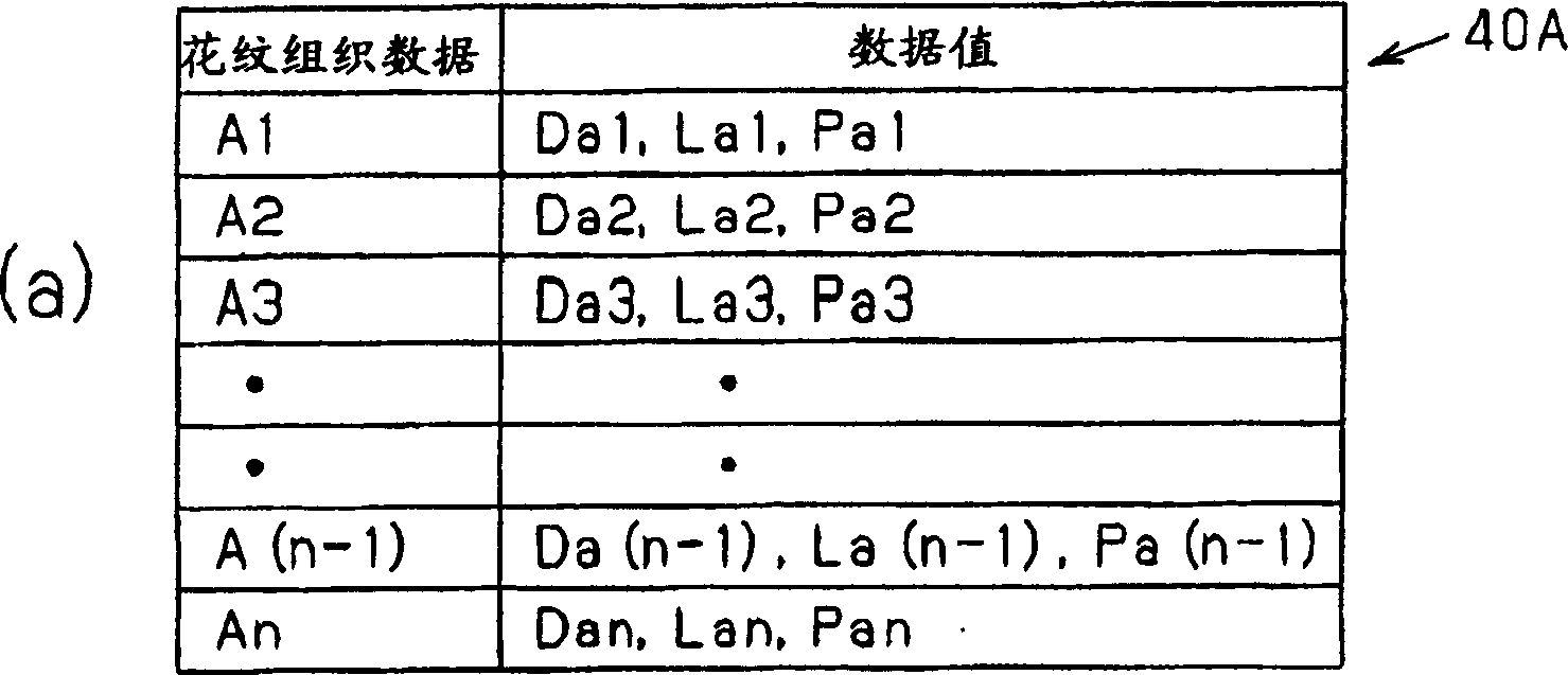
[0045] Next, a second embodiment will be described. In this embodiment, the CPU 24 decides to read the pattern data A1, A2...A(n-1), An and the pattern data B1, B2...B( It differs from the above-mentioned first embodiment in that the rules of the order of k-1) and Bk are different, and that the number of pattern data in the pattern tables 40A and 40B can be the same. Other configurations are the same as those of the above-mentioned first embodiment, and the same components as those of the first embodiment are denoted by the same reference numerals, and descriptions thereof are omitted or simplified.

[0046] In this embodiment, when the number of pattern data in each pattern table 40A, 40B is different, each pattern data is sequentially and alternately read from each pattern table 40A, 40B according to the same rule as in the first embodiment. A1, A2...A(n-1), An and pattern data B1, B2...B(k-1), Bk.

[0047]On the other hand, when the number of pattern data in each of the p...


PUM


Abstract

The special yarn manufacturing apparatus of the present invention performs the speed change of the front roller based on a plurality of pattern data indicating changes in the thickness of the spun yarn, and manufactures a special yarn corresponding to the above pattern data including at least information on the distance between thick pitches. Wire. The CPU controls the first servomotor in accordance with an execution program for executing a repeating pattern of one cycle consisting of pattern data larger in number than the pattern data based on the pattern data stored in the working memory. , thereby spinning a spun yarn that performs a repeated pattern structure of one cycle.

Description

technical field [0001] The present invention relates to a special yarn manufacturing device, in particular to a special yarn manufacturing device for manufacturing (spinning) a special yarn whose yarn thickness is not constant but variable, called a slub yarn or fancy yarn. Background technique [0002] Conventionally, there have been special yarns called slub yarns or fancy yarns in which the thickness of the spun yarn is not constant but the thickness is partially thickened. As shown in Figure 2, the special yarn (slub yarn) SY is manufactured, the thickness (thickness thickness D), length (thickness length L) and spacing ( The internode spacing P) changes. When producing this special yarn, a spinning machine with the same basic configuration as a ring spinning machine is used, and the front roller and the rear roller of the drafting section (drafting device) can be independently variable-speed driven. As a manufacturing device of a special yarn, such a device has been ...

Claims


Application Information

Patent Timeline
IPC IPC(8): D01H5/36D02G3/34
CPCD01H5/36D01H1/22D01H13/32
Inventor 筱崎丰小岛直树
Owner TOYOTA IND CORP
Why Eureka
Try Eureka