Method of controlling electronic cam and servo motor control system

A technology of electronic cam and control method, applied in sequence/logic controller program control, electrical program control, packaging automatic control, etc., can solve problems such as reduced efficiency, vibration, and inability to generate asynchronous cam curves in real time

Active Publication Date: 2006-06-07
ORMON CORP
View PDF1 Cites 41 Cited by
  • Summary
  • Abstract
  • Description
  • Claims
  • Application Information

AI Technical Summary

Problems solved by technology

In particular, as the number of manufactured pieces per unit time increases, the demand for high-speed operation increases, and vibrations are likely to occur near the change point from the asynchronous control area to the synchronous control area, which becomes an obstacle to high-speed control.
[0017] Furthermore, in the method of generating a cam table for electronic cam control offline, the synchronization start position, synchronization range, and synchronization ratio of the synchronization curve in offline are changed, or specific points are passed in order to prevent mechanical interference, etc. Instructions for changing the asynchronous cam curve cannot be generated and carried out in real time, and the cam table needs to be regenerated, which reduces efficiency

Method used


Image

  • Method of controlling electronic cam and servo motor control system
  • Method of controlling electronic cam and servo motor control system
  • Method of controlling electronic cam and servo motor control system

Examples


Embodiment Construction

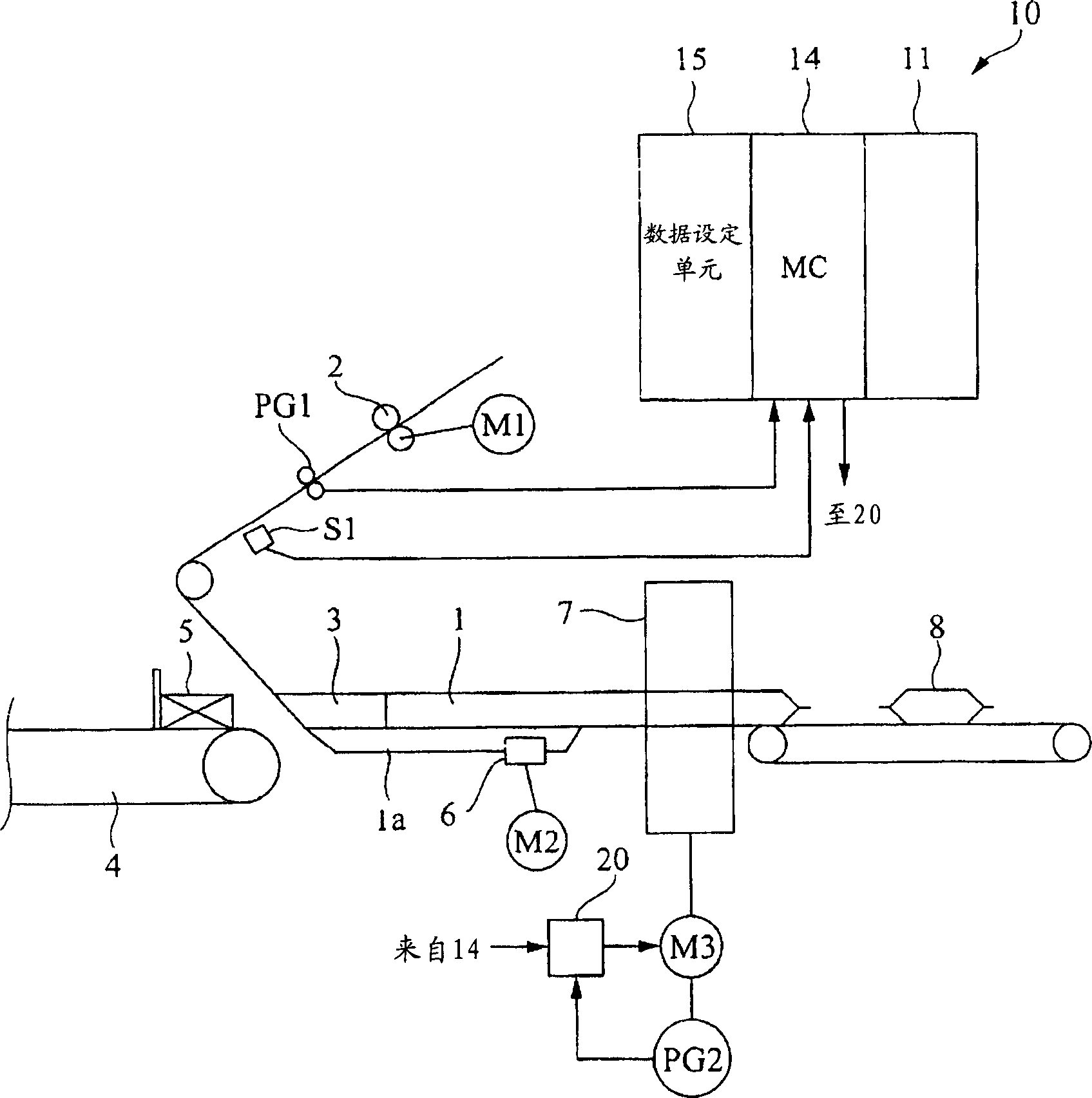
[0067] figure 1 As an example of a control system to which the present invention is applied, a control system for a packaging apparatus is shown. First, the packaging device to be controlled will be described. The packaging film 1 is sandwiched by a pair of feed rollers 2, and is continuously drawn out at a constant speed as the feed rollers 2 rotate. The packaging film 1 thus drawn out is formed into a cylindrical bag by the bag maker 3 . In addition, the packaged objects 5 conveyed at regular intervals with the packaged object conveying and supplying device (finger conveyer) 4 provided on the upstream side of the bag maker 3 are supplied to the bag maker at predetermined timings. 3 inside. Thereby, the to-be-packaged object 5 is contained in the packaging film 1 to be bagged in a cylindrical shape at predetermined intervals, and is conveyed in this state. The center closure device 6 and the end closure device 7 are arranged on the downstream side of the bag maker 3 . Th...


PUM


Abstract

The present invention provides an electronic cam control method in which displacement points, accelerations, and the like can be smoothly connected between a synchronous control section and an asynchronous control section, without vibration. This is a control method of an electronic cam using a servo motor. There is a synchronous control section in which the control object is moved at a constant speed, and an asynchronous control in which the control object is moved from the end position of the synchronous control section to the start position of the next synchronous control section interval, the control in the asynchronous control interval uses a quintic function for the position control of the electronic cam, uses a quartic function for the speed control of the electronic cam, and uses a cubic function for the acceleration control of the electronic cam, so that the control makes the asynchronous The operation of the electronic cam near the change point of switching between the control interval and the synchronous control interval is smooth.

Description

technical field [0001] The invention relates to a control method of an electronic cam and a servo motor control system. Background technique [0002] Various industrial machines such as packaging machines use speed-controllable motors such as servo motors as drive sources. The packaging machine includes: a film supply unit that continuously draws out a tape-shaped packaging film and supplies it to the packaging machine body; a packaged object supply unit that supplies the packaged object to the packaging machine body at predetermined intervals; and the packaging machine body. The main body of the packaging machine is appropriately processed (eg, cylindrical bag making, bag molding) so that the packaged object can be wrapped with the supplied packaging film, and the packaged object is accommodated in the processed packaging film. And the to-be-packaged object is conveyed in the state accommodated in the packaging film, and each package body is manufactured by sealing and cut...

Claims


Application Information

Patent Timeline
IPC IPC(8): G05B19/06B65B51/10B65B57/00
Inventor 前田浩之
Owner ORMON CORP
Why Eureka
Try Eureka