
Method for scalable image transcoding

A transcoding, image technique applied in the field of transcoding images including regions of interest

Inactive Publication Date: 2006-06-07
MITSUBISHI ELECTRIC CORP
View PDF0 Cites 4 Cited by
  • Summary
  • Abstract
  • Description
  • Claims
  • Application Information

AI Technical Summary

Problems solved by technology

This requires rate-distortion recomputation, which is an undesirable feature for real-time image transmission applications

Method used


Image

  • Method for scalable image transcoding
  • Method for scalable image transcoding
  • Method for scalable image transcoding

Examples


Embodiment Construction

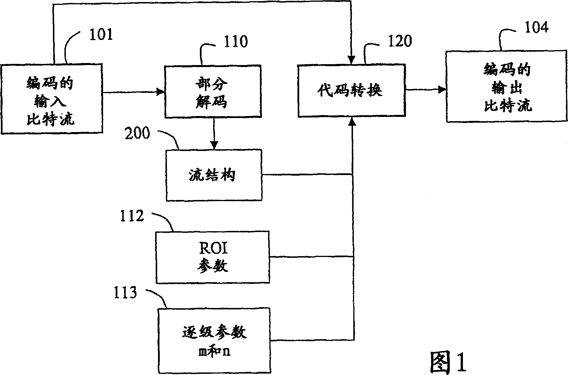
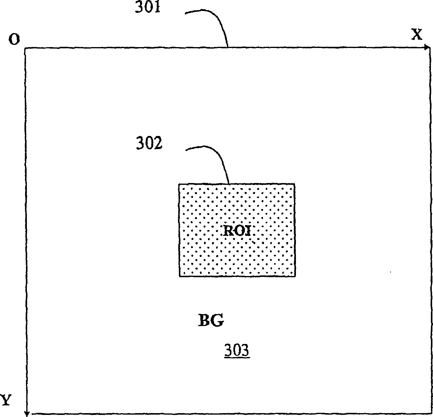
[0024] Figure 1 illustrates a system and method for transcoding an image including a region of interest (ROI) according to the present invention. The ROI is a rectangular area in the image. The input to the system is an encoded bitstream 101, eg a JPEG 2000 bitstream. The bitstream is in the form of a sequence of data packets. These images can be compressed using lossy or lossless techniques.

[0025] During encoding of the bitstream 101, the image is analyzed into four sub-band images using a wavelet transform in the JPEG 2000 standard. The subband image includes coefficients describing different spatial frequency characteristics of the subband image. The lowest frequency subband image is further decomposed into four smaller subbands. This process can be repeated as necessary to achieve the desired image resolution. Each subband image is divided into non-overlapping rectangular blocks, called "code blocks". Each code block is independently encoded into a final encoded b...


PUM


Abstract

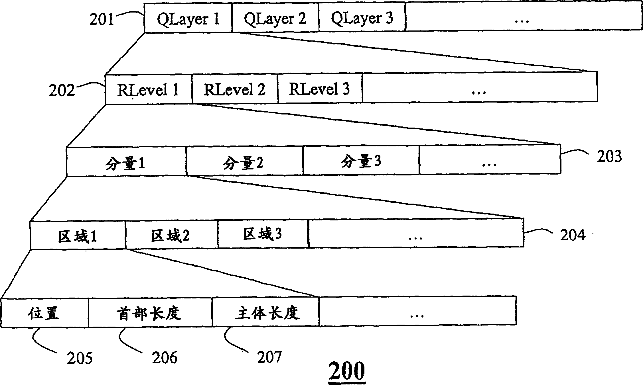
A method to transcode an image in the form of an input bitstream. The input bitstream includes quality layers, each quality layer includes resolution levels, each resolution level includes components, each component includes regions, and each region includes a packet segmentation position, a header length, and a body length. The input bitstream is partially decoded to obtain the structure of the encoded input bitstream. Specify the coordinates of the region of interest in the image, and define step-by-step parameters. The partially decoded input bitstream is then encoded according to the structure, coordinates and stage parameters to obtain an encoded output bitstream.

Description

technical field [0001] The present invention relates generally to image and video coding, and in particular to transcoding images including regions of interest. Background technique [0002] Video surveillance, cellular telephones, digital cameras, printers, scanners, fax machines, copiers, medical imaging, satellite imaging, the Internet, and compound documents have increased the demands on image and video applications. However, high quality images are often not possible due to constrained resources such as bandwidth, memory and processors. The quality of an image depends on the number of pixels in the image, and the number of bits allocated to each pixel. For example, a 1024x1024 pixel image with 24 bits per pixel would be a 25Mb high quality color image, while a 10x10 pixel image with 1 bit per pixel would be a 100 bits low quality black and white thumbnail. [0003] One solution distinguishes a region of interest (ROI) in an image from the background (BG). Uses more b...

Claims


Application Information

Patent Timeline
Patent Type & Authority Applications(China)
IPC IPC(8): H04N7/30
CPCH04N21/234345H04N19/70H04N19/647H04N19/63H04N19/132H04N19/146H04N19/154H04N19/162H04N19/17H04N19/187H04N19/64H04N19/40H04N19/188
Inventor 孔浩松安东尼·韦特罗秦淑彦桑原直树
Owner MITSUBISHI ELECTRIC CORP
Learn More