Scanning laser microscope with wave-front sensor

A technology of scanning microscope and wavefront sensor, applied in the field of scanning laser microscope

Inactive Publication Date: 2006-06-07
3M INNOVATIVE PROPERTIES CO
View PDF3 Cites 13 Cited by
  • Summary
  • Abstract
  • Description
  • Claims
  • Application Information

AI Technical Summary

Problems solved by technology

The typical diffraction limit, which determines the resolution of the microscope, is based on the integration of the collected light

Method used


Image

  • Scanning laser microscope with wave-front sensor
  • Scanning laser microscope with wave-front sensor
  • Scanning laser microscope with wave-front sensor

Examples


Embodiment Construction

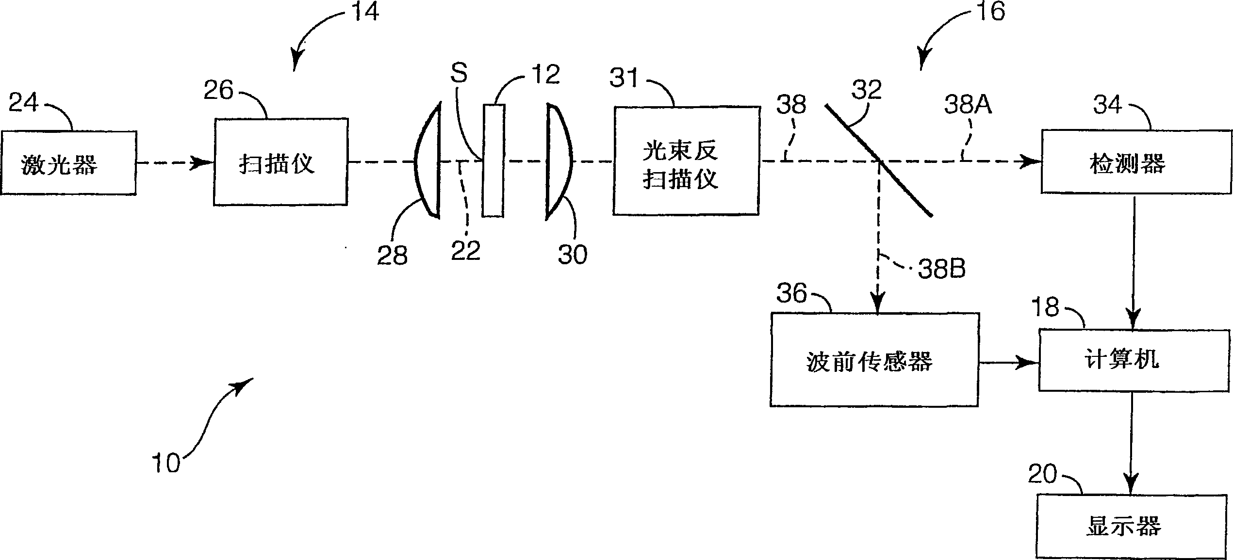
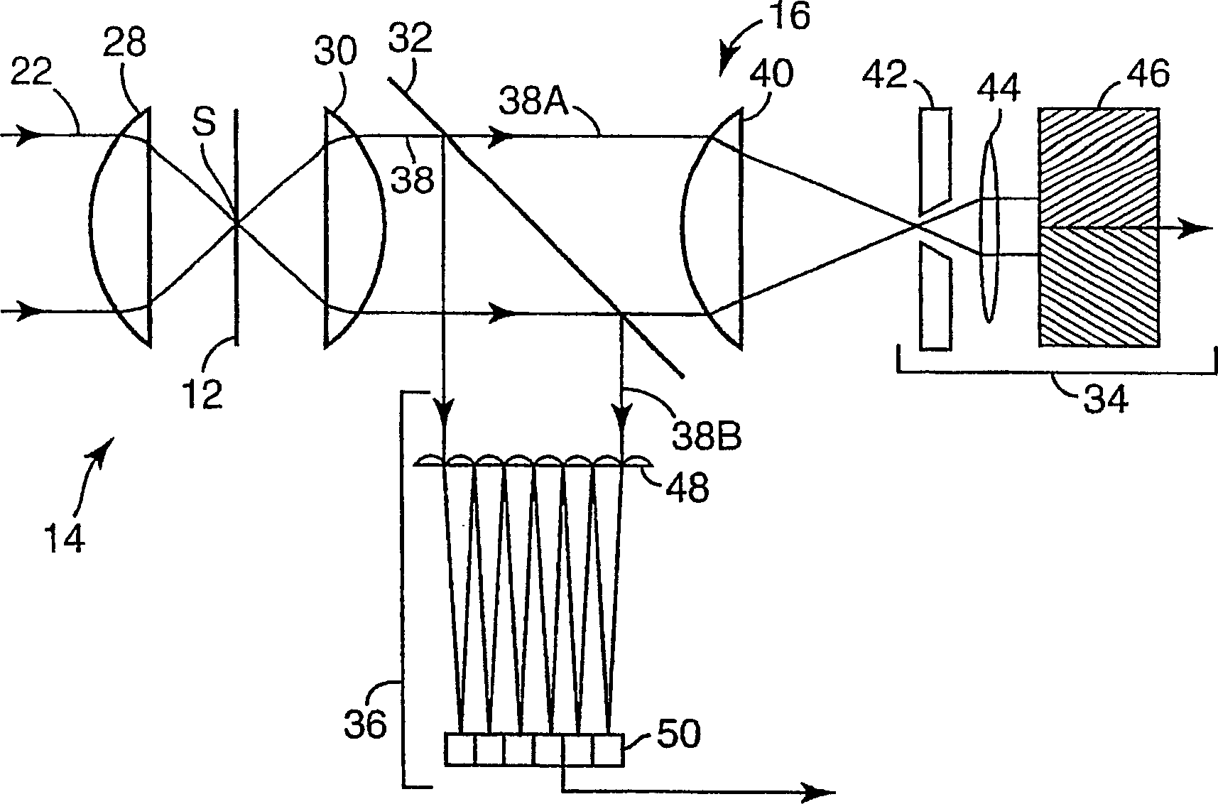
[0023] The present invention is an improved scanning laser microscope that includes a wavefront sensor for detecting phase changes in light from a target location in an object. This phase change represents the wavefront shape of the light rays collected at each scanned pixel location in the target area. From this wavefront shape, a high-frequency spectrum corresponding to the uncollected scattered light can be derived. This scattered light is produced by scanning small-scale features at the pixel locations. Based on the high frequency spectra of these scanned pixel locations, an enhanced resolution image of the target area can then be generated.

[0024] The invention is based on the recognition that more information is present in the acquisition light in the detection arm of a scanning laser microscope than in conventionally used microscopes. By using a wavefront sensor in conjunction with conventional detection methods, the portion of the spatial frequency above the system...


PUM


Abstract

An enhanced resolution image of the object is produced by a scanning laser microscope (10) that includes an illumination arm (14) for scanning the object (12) by a focused probe beam (22) and a detection arm for receiving light from the object (16). The detection arm includes a detector (34) that collects and detects light from the object (12) to generate pixel data for a plurality of pixels. Additionally, the detection arm includes a wavefront sensor (36) for detecting phase changes of light from the object to generate wavefront data for the scanned pixel locations. From the wavefront shape of the light collected at each pixel location, a high frequency spectrum can be determined, which corresponds to the uncollected light diffracted from small scale features at that pixel location. Based on the high frequency spectrum of these scanned pixel locations, an enhanced resolution image of the target area is produced.

Description

technical field [0001] The present invention relates to scanning laser microscopes. In particular, the invention relates to scanning laser microscopes equipped with wavefront sensors to acquire wavefront data from scanned pixel locations. The wavefront data collected from the wavefront sensor can be used to generate enhanced resolution images. Background technique [0002] A known scanning laser microscope includes an illumination arm and a detection arm. The illumination arm generates a focused probe beam which is scanned over the sample or object. While scanning, reflected, scattered or emitted light is collected and detected for imaging on a pixel-by-pixel basis. The detection arm of the microscope may include spectral filters (for fluorescence or photoluminescence imaging), spatial filters (for confocal imaging) and / or polarization analyzers (for polarization imaging). [0003] The detection arm of a scanning laser microscope includes an objective lens that collects ...

Claims


Application Information

Patent Timeline
Patent Type & Authority Applications(China)
IPC IPC(8): G02B21/00
CPCG02B21/002G02B21/00G02B21/06G02B21/14
Inventor 马修·R·C·阿特金森
Owner 3M INNOVATIVE PROPERTIES CO
Why Eureka
Try Eureka