Dust remover of vacuum cleaner

A dust removal device, vacuum cleaner technology, applied in the direction of suction filter, etc., can solve the problems of poor separation effect between air and coarse dust, shorten the service life of Hypa, increase the filtration capacity of Hypa, etc., to improve the separation efficiency of the first level, strengthen the strength, The effect of improving dust removal efficiency

Active Publication Date: 2006-06-21
KINGCLEAN ELECTRIC
View PDF0 Cites 12 Cited by
  • Summary
  • Abstract
  • Description
  • Claims
  • Application Information

AI Technical Summary

Problems solved by technology

Since Hypa needs to be installed in the net cover, the space between the outer wall of the net cover and the inner wall of the cup is small, and the formed cyclone

Method used


Image

  • Dust remover of vacuum cleaner
  • Dust remover of vacuum cleaner
  • Dust remover of vacuum cleaner

Examples


Example Embodiment

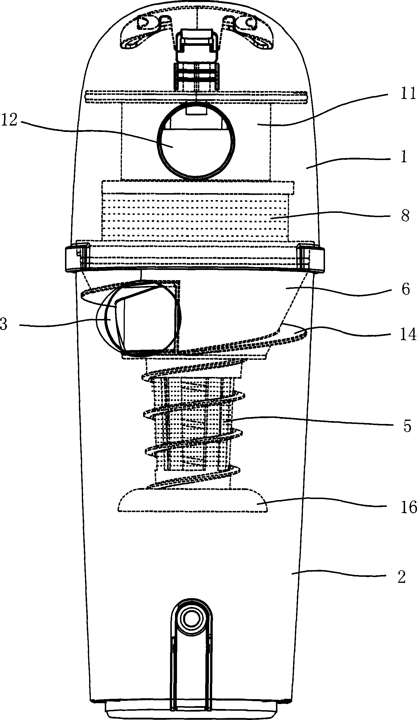
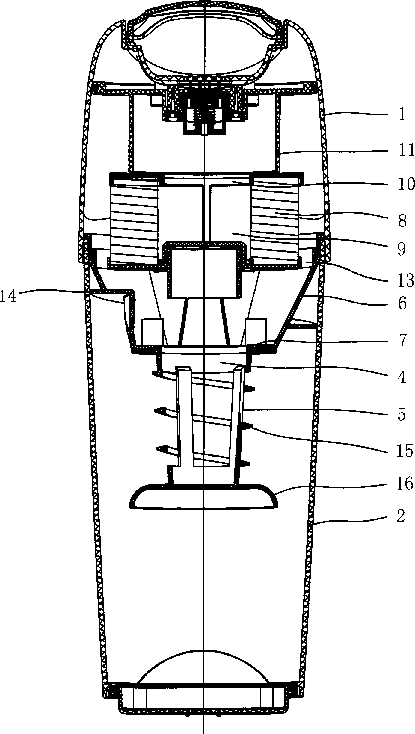
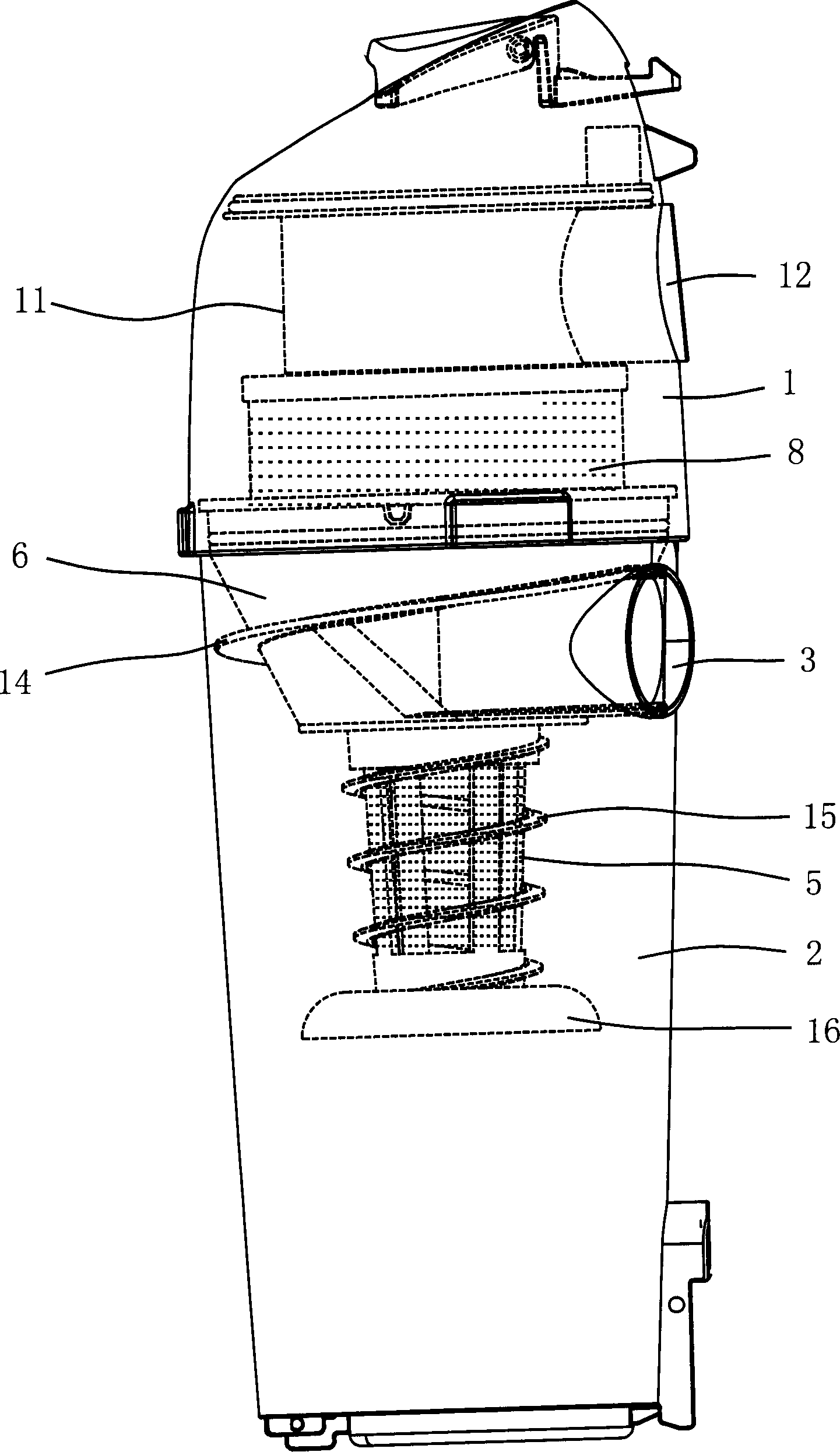
[0019] Example: such as figure 1 , figure 2 , image 3 , Figure 4 , Figure 5 As shown, a dust removal device for a vacuum cleaner includes a cup cover 1 and a cup body 2. The cup cover 1 is provided with an air outlet 12, and the cup body 2 is provided with an air inlet 3. The cup cover 1 is a transparent body, or a cup The cover 1 is provided with a perspective window, and a partition plate 6 is provided between the cup cover 1 and the cup body 2. The partition plate 6 is in the shape of a cone with a large upper end and a small lower end. The partition plate 6 is provided with an opening 7 for opening The bottom of the hole 7 is connected with a net cover 5, the upper end of the net cover 5 is provided with an opening 4, the opening 4 is docked with the opening 7 on the partition plate 6 and is fixed, and the cup cover 1 above the partition plate 6 is equipped with a cylindrical sea. Handkerchief 8, a gap 13 is provided between the inner wall of the partition plate 6 ...


PUM


Abstract

The dust eliminating device for dust collector includes one cup cover and a cup body, as well as a separating plate with hole and netted cover with opening corresponding to the hole in the separating plate set between. The cup cover has an inside tubular Hy-Pak ring, the tubular Hy-Pak ring has a central hole with closed lower end and opened upper opening, and an air outlet hood communicated to the air outlet is set on the opened upper opening. The present invention has Hy-Pak ring set inside the cup cover, rather than cup body, and this expands the space between the netted cover and the cup body, enhanced cyclone strength, raised first stage separating efficiency, reduced filtering amount of the secondary Hy-Pak separation, and prolonged Hy-Pak ring life. In addition, the cup cover is transparent or is provided with transparent window for direct observation of the Hy-Pak ring in use.

Description

technical field [0001] The invention relates to a dust removal device of a vacuum cleaner. Background technique [0002] At present, the dust cup of the vacuum cleaner generally includes two parts: the cup cover and the cup body. The air outlet on the cup cover is connected. When in use, the air containing dust enters the dust cup from the air inlet, and forms a whirlwind in the dust cup. The coarse dust is filtered out by the first-stage separation of the net cover, and then enters the inner cavity of the net cover, and then the fine dust is filtered out by the second-level separation of Hypa. Finally, it enters the cup cover from the upper port of the Hypa, and finally discharges from the air outlet on the cup cover. Since Hypa needs to be installed in the net cover, the space between the outer wall of the net cover and the inner wall of the cup is small, and the formed cyclone is not strengthened, which makes the separation effect of air and coarse dust poor, thus incre...

Claims


Application Information

Patent Timeline
IPC IPC(8): A47L9/16
Inventor 倪祖根
Owner KINGCLEAN ELECTRIC
Why Eureka
Try Eureka