Electronic expansion valve

An electronic expansion valve and valve seat technology, which is applied in the direction of valve lift, valve details, valve device, etc., can solve the problems of large axial size of stopper parts, decline of coil insulation performance, and occupation of installation position, etc., and achieves compact structure, Work smoothly, small size effect

Inactive Publication Date: 2006-06-21
ZHEJIANG SANHUA CO LTD
View PDF1 Cites 35 Cited by
  • Summary
  • Abstract
  • Description
  • Claims
  • Application Information

AI Technical Summary

Problems solved by technology

Yet this scheme at least also has the following disadvantages: (1), the cooperation between the screw mandrel and the screw sleeve of its magnetic rotor part requires flexible rotation, so there is usually a certain gap between the screw mandrel and the screw sleeve. There is a magnetic rotor component that will deviate from its designed action position when it rotates (such as swinging relative to the axis of the valve body), thereby generating vibration and noise; (2) When the magnetic rotor component drives the valve stem up and down, the valve stem and There will be mutual rotation between the screw rods, and the spring supported at the rear end of the valve rod will hinder the rotation due to

Method used


Image

  • Electronic expansion valve
  • Electronic expansion valve
  • Electronic expansion valve

Examples


Embodiment Construction

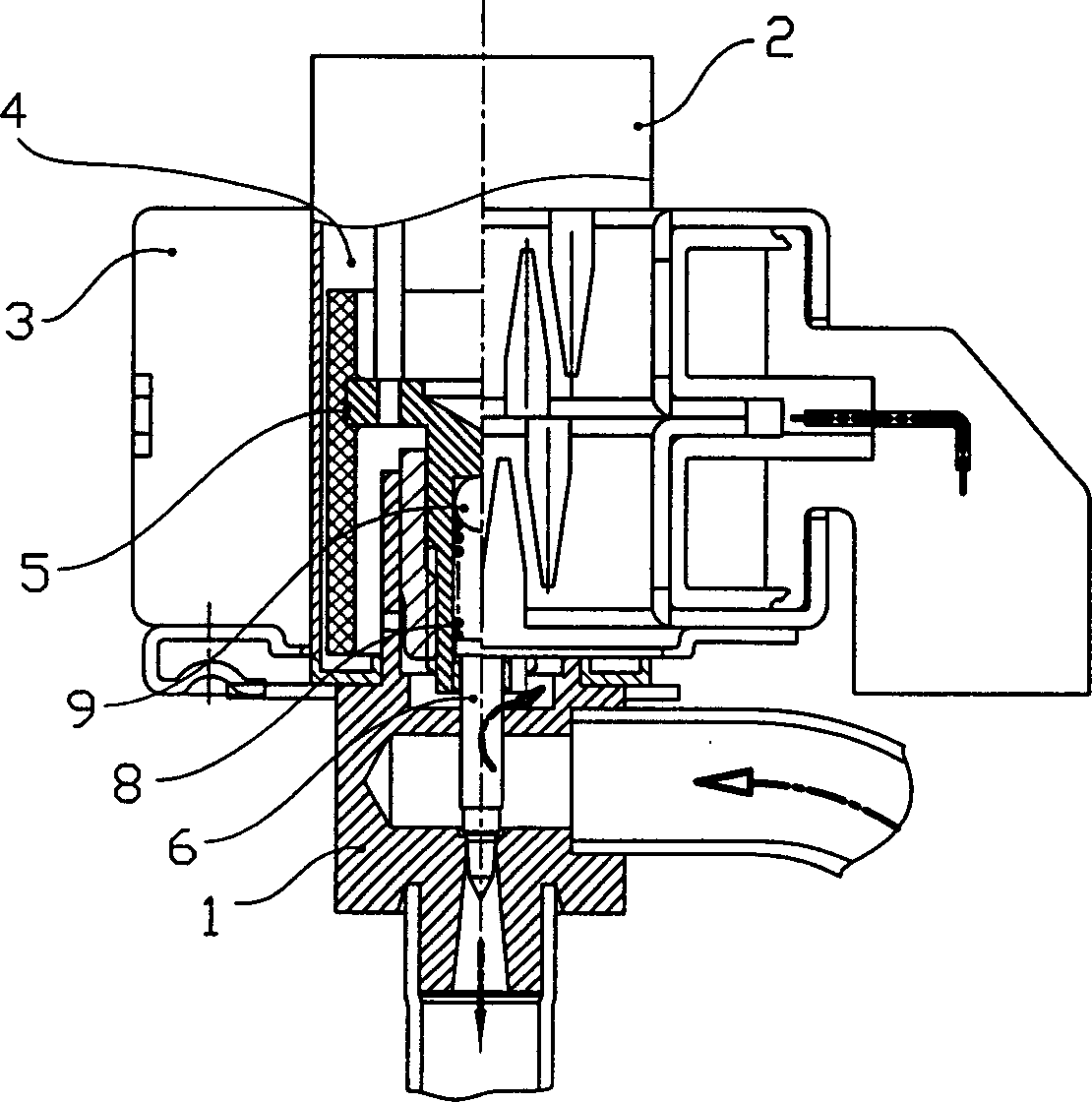
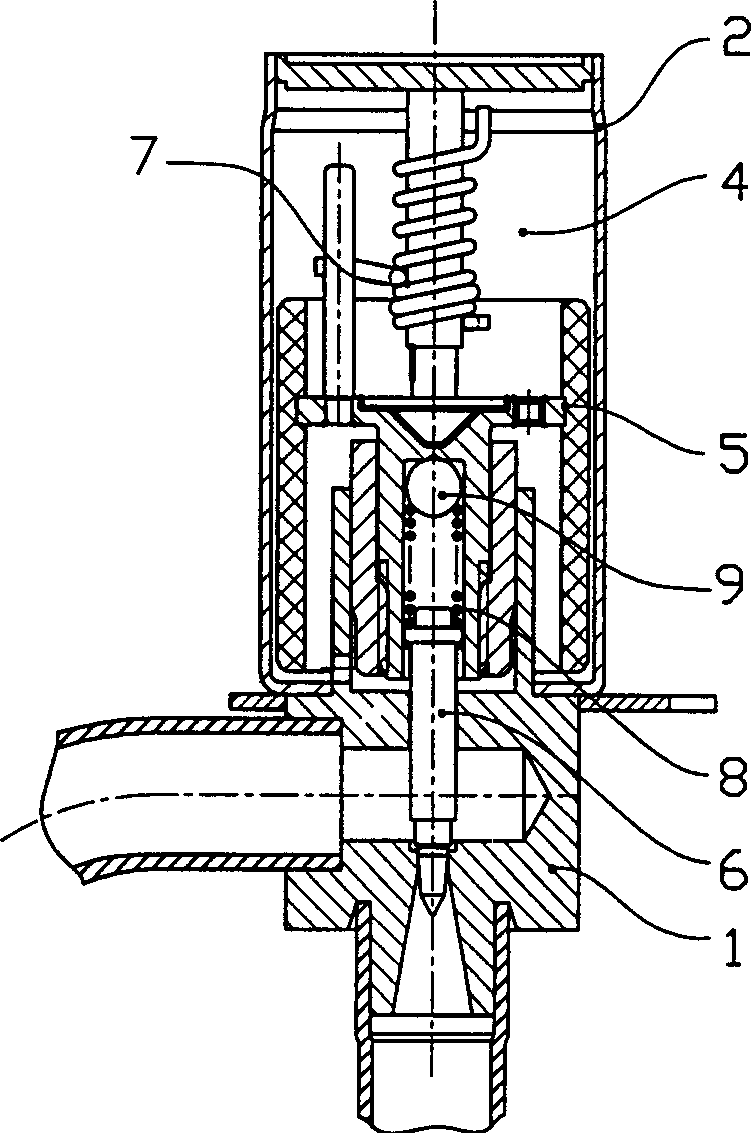
[0028] Such as figure 1 The electronic expansion valve shown mainly includes a valve seat 1, a sleeve 2, a magnetic rotor part 5, a valve stem 6, a stopper part 7 and a coil 3, wherein:

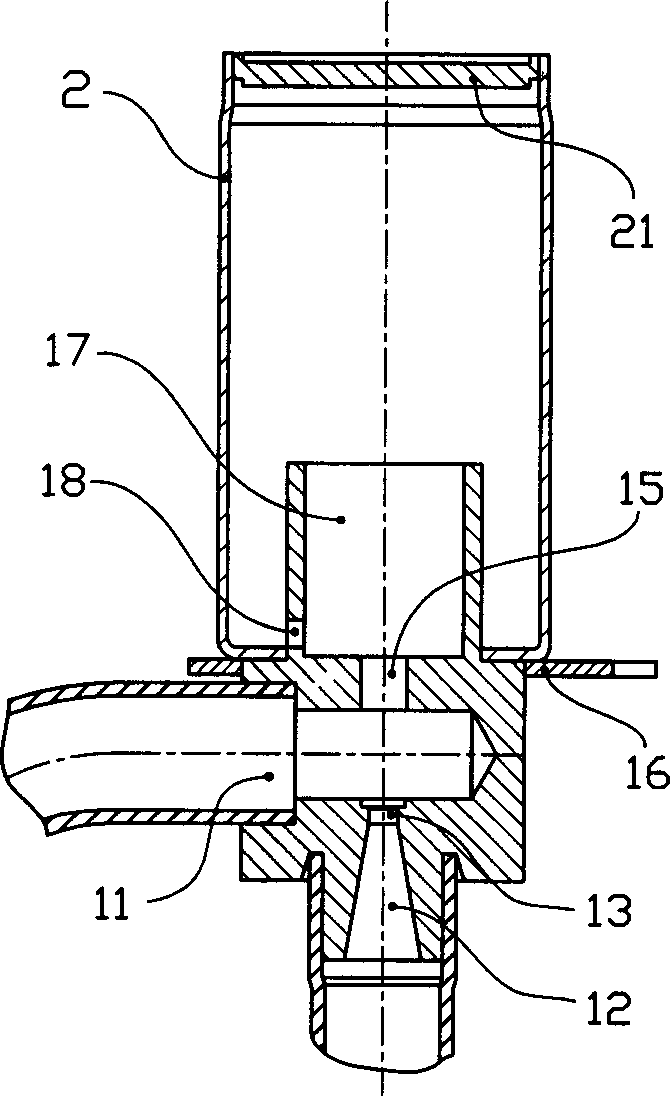
[0029] Such as Figure 9 As shown, the valve seat 1 is provided with an inlet 11, an outlet 12, and a valve port 13 connecting the inlet and the outlet. And the flare angle α adjacent to the valve port is 15 ~ 25 ° bell mouth (see details Figure 9 ), the valve seat 1 is provided with a fixing hole 17, and the fixing hole 17 is press-fitted with a nut 14 through an interference fit. Figure 8 ), the side wall of the fixing hole 17 is provided with a pressure balance hole 18 communicating with the fixing hole and its outer cavity 4, and the valve seat 1 is also provided with a guide hole 15 corresponding to the valve port; the valve seat 1 is welded with The fixed frame 16 is provided with evenly distributed clamping points 16a on the fixed frame 16, and the pitch angle of the clamping poin...


PUM


Abstract

This invention relates to one electrical expansion valve, which comprises valve socket, coils connected to the valve cover tube and cover tube, wherein, the valve socket is opened with entrance and exit mouth and valve mouth connected; the said cover tube and valve socket form sealed chamber with one magnetic rotor part to sense the said coil magnetic rotation and to convert into axle direction; the magnetic rotor down end is located with one valve bar to lift with the said valve with top end located inside cover tube to match with brake part; the said valve socket is fixed with one screw and the rotor is set with one wire bar.

Description

【Technical field】 [0001] The invention relates to a rotary electronic expansion valve, which is used for flow control of refrigerant medium flowing through the valve body. 【Background technique】 [0002] The current rotary electronic expansion valve uses the principle of a stepping motor to drive the magnetic rotor part to rotate forward and reverse with a coil, and the magnetic rotor part drives the valve stem up and down to change the flow area of ​​the valve port, so as to realize the cooling of the flow through the valve port. The flow of the agent medium is controlled according to the predetermined flow-pulse curve, and the invention patent with the authorized notification number CN2637833Y represents the more advanced technical solution of this electronic expansion valve. Yet this scheme at least also has the following disadvantages: (1), the cooperation between the screw mandrel and the screw sleeve of its magnetic rotor part requires flexible rotation, so there is us...

Claims


Application Information

Patent Timeline
IPC IPC(8): F16K1/00F16K31/04
Inventor 张胜昌吕铭
Owner ZHEJIANG SANHUA CO LTD
Why Eureka
Try Eureka