Unlock instant, AI-driven research and patent intelligence for your innovation.

Robot controller

A control device and robot technology, applied in program control, general control system, control/regulation system, etc., can solve the problems of waste of manipulators and longer cycle time, etc.

Inactive Publication Date: 2006-06-28
FANUC LTD
View PDF0 Cites 9 Cited by
  • Summary
  • Abstract
  • Description
  • Claims
  • Application Information

AI Technical Summary

Problems solved by technology

As a result, the movement of the robot is wasted and the cycle time becomes longer.

Method used


Image

  • Robot controller
  • Robot controller
  • Robot controller

Examples


Embodiment Construction

[0018] Hereinafter, the best mode for carrying out the present invention will be described with reference to the drawings.

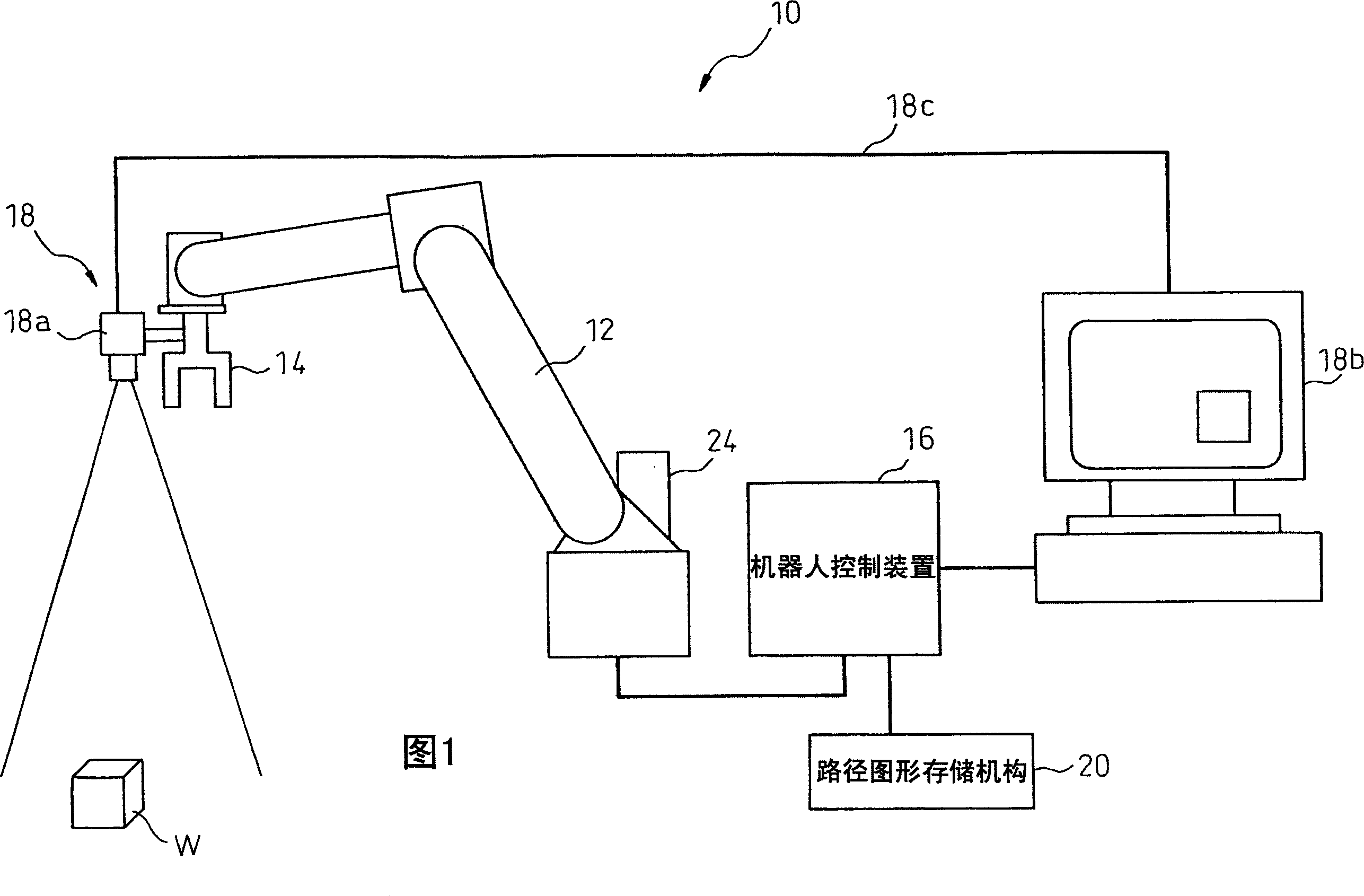
[0019] First, an overall configuration of a robot system 10 using a robot control device 16 of the present invention will be described with reference to FIG. 1 . The robot 10 system has: a robot arm 12; a manipulator 14 installed at the front end of the robot arm 12; a robot control device 16 for controlling the actions of the robot arm 12 and the manipulator 14; a visual sensor 18 for detecting the position of the workpiece W; and a path graph for storing The path pattern storage mechanism 20 makes the manipulator 14 close to the workpiece W placed on the workpiece placement table 22 such as a conveyor or a workbench, holds the workpiece W with the manipulator 14, and then transports the workpiece W to another place.

[0020] The robot arm 12 is of a known type, and is configured to be able to move the manipulator 14 to a predetermined position in respo...


PUM


Abstract

The present invention relates to a robot control device. First, a specific target position is selected to set the approach path and departure path of a manipulator. As the approach path and departure path of the manipulator relative to the selected specific target position, different multiple The path pattern is stored in the path pattern storage mechanism. Secondly, based on the workpiece position detected by the vision sensor, one path pattern is selected from multiple path patterns stored in the path pattern storage mechanism. In order to make the target position that the manipulator should move towards consistent with the actual workpiece position, the selected path pattern is corrected. The path pattern is defined as an approach path and a departure path, and the manipulator is moved along the prescribed approach path and departure path.

Description

technical field [0001] The invention relates to a robot control device, which uses a visual sensor to detect the position of a workpiece, and according to the detected position of the workpiece, corrects the target position that the manipulator should face, so that the manipulator approaches or leaves relative to the workpiece. Background technique [0002] In the robot system, it is necessary to specify the reference position in advance. On the premise that the workpiece is arranged at the reference position, the approach path or departure path of the manipulator relative to the workpiece is taught, and the movement of the manipulator is specified. The teaching of such a path is obtained by direct teaching of directly moving the manipulator along the path, or indirect teaching of specifying the start point, passing point, and end point on the path, and obtaining the orbit between them by interpolation. [0003] However, it is actually difficult to arrange the workpiece accu...

Claims


Application Information

Patent Timeline
Patent Type & Authority Applications(China)
IPC IPC(8): B25J13/08B25J9/10
CPCB25J9/1664G05B2219/40431G05B2219/40564G05B2219/45063
Inventor 秋山和彦小林博彦
Owner FANUC LTD