Rolling type internal combustion engine

An internal combustion engine, a new type of technology, applied in the direction of machines/engines, mechanical equipment, etc., can solve problems such as complex structures, and achieve the effects of high energy conversion rate, simple structure, and large force arm

Inactive Publication Date: 2006-06-28
何荣灿
View PDF1 Cites 5 Cited by
  • Summary
  • Abstract
  • Description
  • Claims
  • Application Information

AI Technical Summary

Problems solved by technology

However, this structure is relatively complicated because the ratchet is arranged inside the box and the unloading discs are double discs.

Method used


Image

  • Rolling type internal combustion engine
  • Rolling type internal combustion engine
  • Rolling type internal combustion engine

Examples


Embodiment Construction

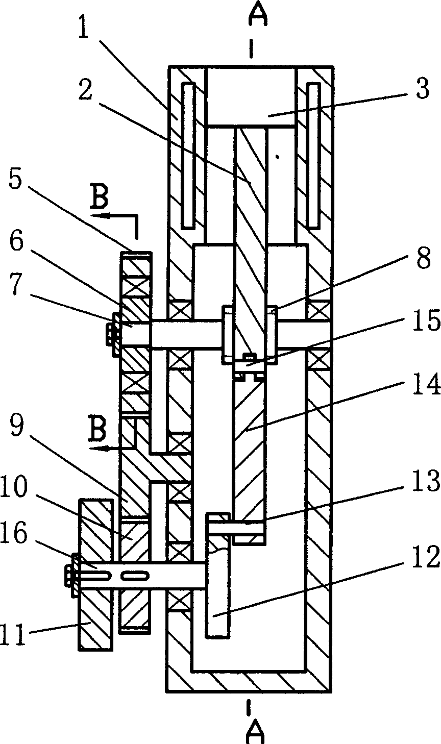
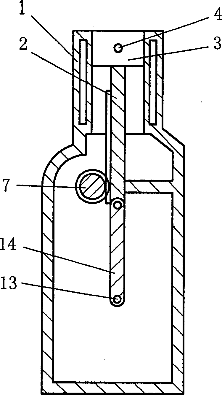
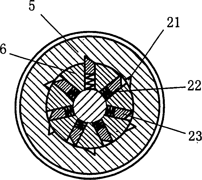
[0025] see figure 1 , figure 2 , image 3 Shown is the first embodiment of the new rubbing internal combustion engine of the present invention, which includes a gas distribution device, an intake and exhaust device, a fuel supply system, a lubrication system, a cooling system, a cylinder block 1, a piston 3, a power transmission mechanism, an unloading The force device, the piston 3 is arranged in the inner cavity of the upper end of the cylinder 1. The power transmission mechanism includes a push rod 2, a ratchet shaft 7, an inner wheel 6, a ratchet mechanism, a ratchet 5, and a transition gear shaft 9. The piston 3 is fixed on the upper end of the push rod 2 through the piston pin 4, a rack is provided on one side of the push rod 2, the ratchet shaft 7 is supported on the cylinder body 1 through a bearing, and the right outer cylindrical surface of the ratchet shaft 7 is An external tooth 8 is arranged on the top, and this external tooth 8 meshes with the rack on the side ...


PUM


Abstract

The invention is a novel twisting internal combustion engine, on the basis of an original reciprocating internal combustion engine, adding ratchet wheel shaft, inner wheel, ratchet mechanism, ratchet wheel, transition gear shaft, force release disc drive gear, force release disc shaft, link rod, and fly wheel, and changing the original link rod into a push rod provided with a rack on the side surface, where the rack engages with the gear on the ratchet wheel shaft; in the word doing course, piston and the push rod go down to push the ratchet wheel to rotate, the moving direction of the piston is always kept to be the tangential direction of the circumference of the ratchet wheel so that the moment is large, and the remaining travel is implemented by depending on fly wheel inertia to make the push rod reciprocate through the force release disc shaft and the link rod, therefore the energy conversion ratio is high, achieving unloading purpose. By setting the ratchet mechanism to be a reduced tooth or pawl mechanism, it can largely reduce clearance joints.

Description

【Technical field】 [0001] The invention relates to an internal combustion engine, in particular to a reciprocating rubbing internal combustion engine. 【Background technique】 [0002] At present, the reciprocating internal combustion engine widely used by people has a cylinder, a piston, an intake valve, an exhaust valve, an ignition device, a crank connecting rod device and a fuel supply device. The rotary motion and energy conversion are realized by the crank linkage mechanism. Since the moving direction of the piston is not the tangential direction of the rotation circle of the crankshaft, the force of the crankshaft rotation is constantly changing with the progress of the compression stroke, so the rotation of the crankshaft is uneven. On a four-stroke engine, the crankshaft rotates two weeks, Only half a cycle is under force to do work, and the remaining one and a half weeks not only does not receive force to do work, but also is affected by the resistance produced by th...

Claims


Application Information

Patent Timeline
Patent Type & Authority Applications(China)
IPC IPC(8): F02B75/40F02B61/06
Inventor 何荣灿
Owner 何荣灿
Why Eureka
Try Eureka