Direct type back light module

A backlight module, direct type technology, applied in optics, nonlinear optics, mirrors, etc., can solve the problems of dark band overall backlight module light, the uniform effect of light is not easy to control, and the uniformity is not enough.

Inactive Publication Date: 2006-06-28
AU OPTRONICS CORP
View PDF0 Cites 35 Cited by
  • Summary
  • Abstract
  • Description
  • Claims
  • Application Information

AI Technical Summary

Problems solved by technology

[0008] However, since there is no light source at the corners or edges of the above-mentioned direct-lit backlight module structure, dark bands are likely to appear in the corners or edges or the light of the overall backlight module is not uniform enough.
If the corners or edges of the direct-type backlight module structure are provided with particularly dense light sources, the structural complexity and cost of the LED array will be significantly increased, and the desired light uniformity effect is not easy to control.

Method used


Image

  • Direct type back light module
  • Direct type back light module
  • Direct type back light module

Examples


Embodiment Construction

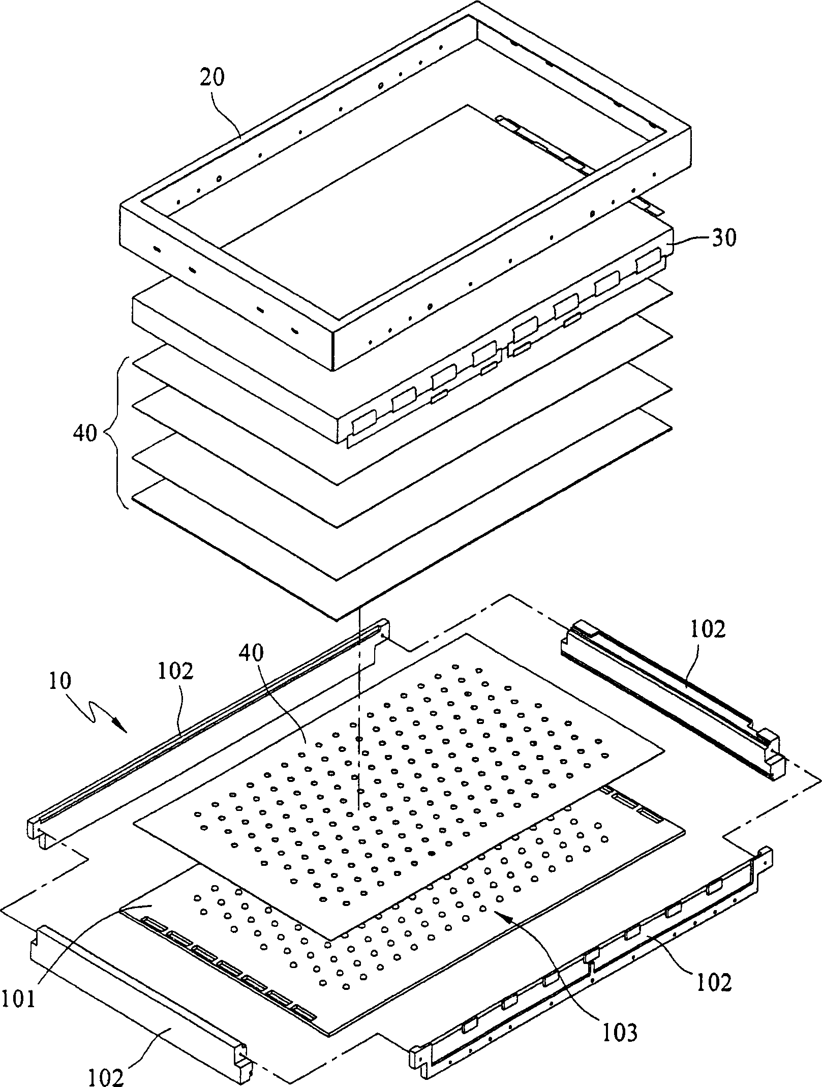
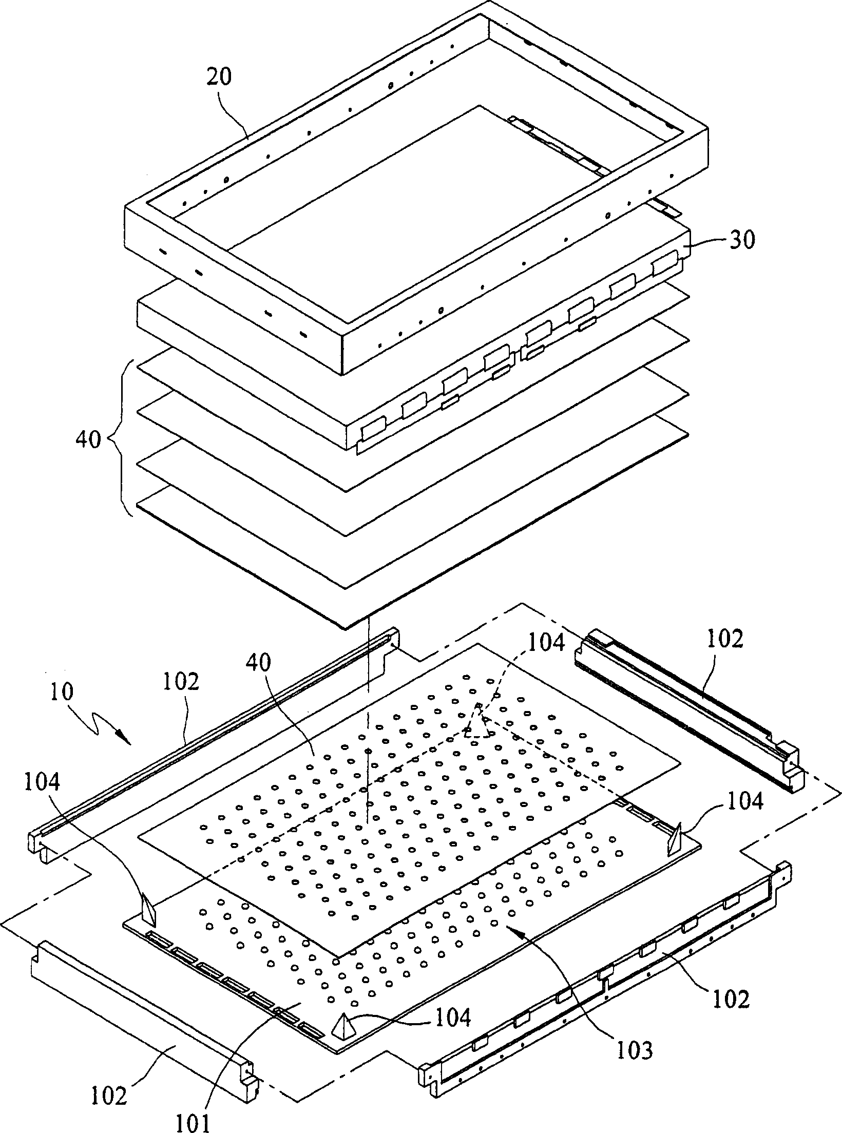
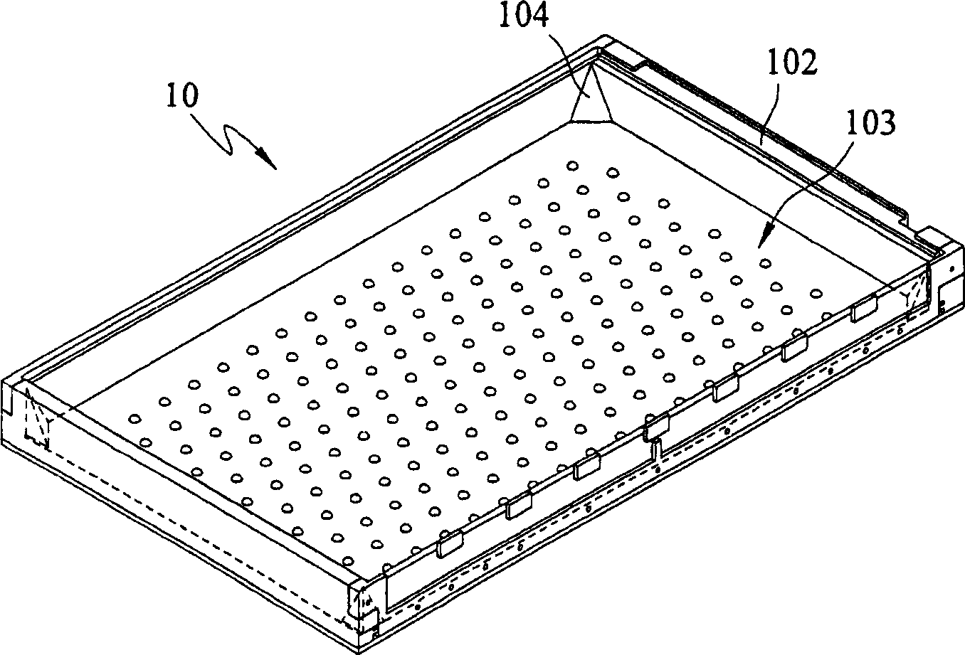
[0032] figure 2 Describe the three-dimensional exploded schematic view of the liquid crystal display of the present invention, the liquid crystal display of the present invention has a liquid crystal panel 30, a front frame 20, is arranged on this liquid crystal panel 30 and fixes it, a backlight module 10, has at least one light source, the best The light source is a light emitting diode array 103, which is arranged on the back plate 101, and a frame body 102, which is arranged on at least two adjacent edge areas of the back plate 101, and defines at least one corner area together with the back plate 101; the liquid crystal A plurality of optical films 40 are arranged between the panel 30 and the backlight module 10 to increase light utilization and efficiency. The plurality of optical films 40 can be diffusion sheets, prism sheets, acrylic optical sheets, brightness enhancement sheets or combinations thereof.

[0033] The corner area of ​​the backplane 101 is provided with ...


PUM


Abstract

A back light module of straight down type sets reflection structure at corner of back light module to improve dark zone at corner or edge of back light module for making integral brightness of back light module be uniform.

Description

technical field [0001] The invention relates to a light-emitting diode backlight module, in particular to a direct-lit backlight module for a liquid crystal display, which is suitable for avoiding dark bands at the corners or edges of the backlight module and making the brightness of the backlight module more uniform . Background technique [0002] Liquid crystal display (LCD) has largely replaced the traditional cathode ray tube (CRT) display due to its thinness and fine picture quality. The backlight module is a very important light-emitting structure in the liquid crystal display. By controlling the light source provided by the backlight module, coordinating with the liquid crystal in the liquid crystal panel, and properly controlling the switch components, the brightness and quality of the display screen of the liquid crystal display are determined. [0003] Due to the advantages of low power consumption, small size and high brightness, LEDs have replaced traditional fl...

Claims


Application Information

Patent Timeline
Patent Type & Authority Applications(China)
IPC IPC(8): G02F1/1335G02B5/08
Inventor 萧孟佳周信宏
Owner AU OPTRONICS CORP
Why Eureka
Try Eureka