Method of increasing electric appliance power factor

A reactance and electric welding machine technology, applied in the direction of inductors, variable inductors, transformers/inductor coils/windings/connections, etc., can solve the problem that the power factor will not be improved, the power factor is not high, and the reactance value is not good. Change and other problems, to achieve arc stability, improve power factor, increase the effect of output capacity

Inactive Publication Date: 2006-06-28
蒋风岐 +1
View PDF0 Cites 4 Cited by
  • Summary
  • Abstract
  • Description
  • Claims
  • Application Information

AI Technical Summary

Problems solved by technology

[0002] At present, electrical products with coils have been widely used in industrial production and people's lives, such as: electric welding machines, transformers, motors, etc., the power factor of these products is not high, wasting a lot of precious energy in vain
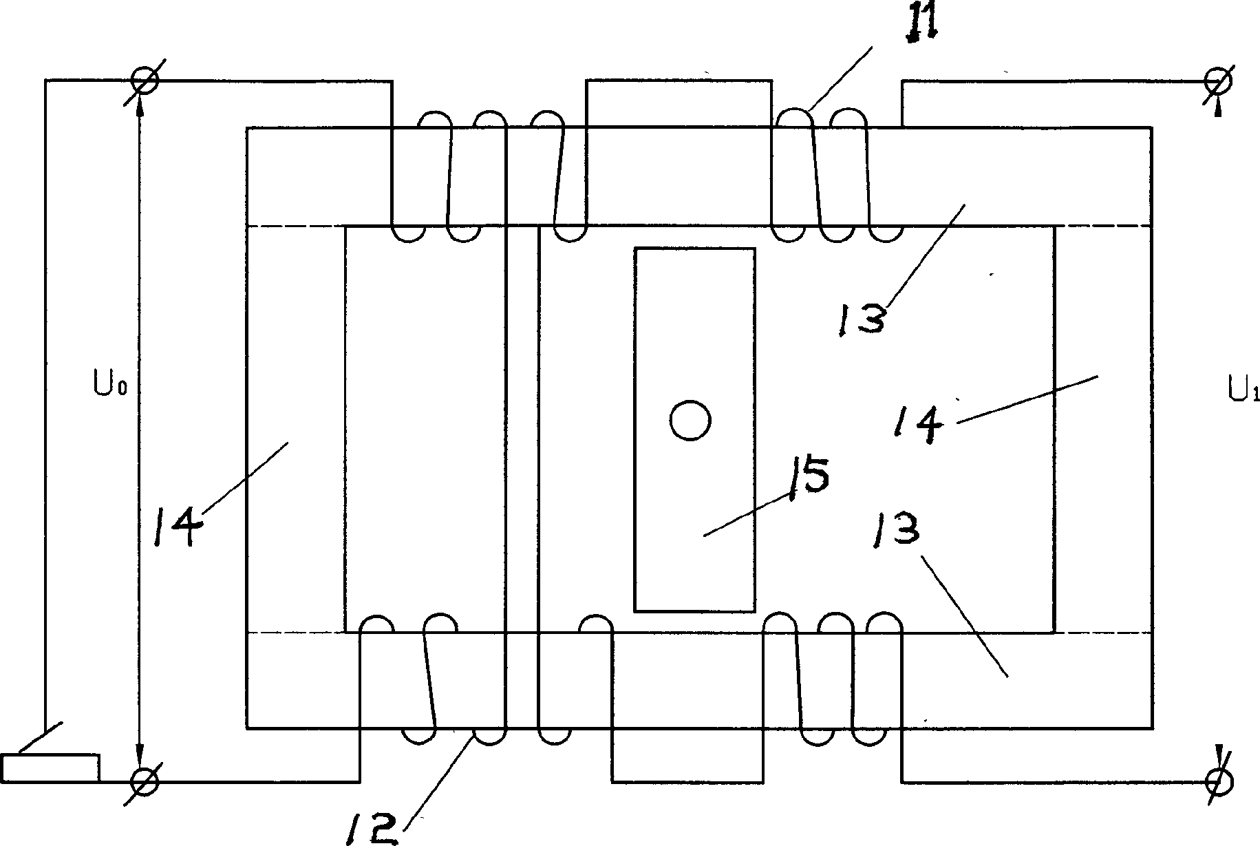
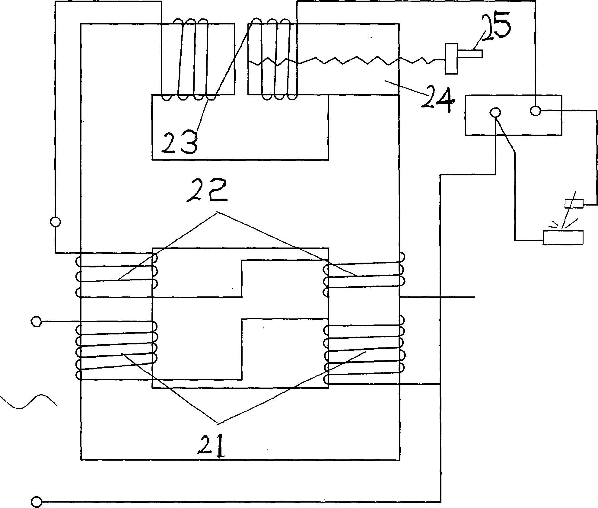
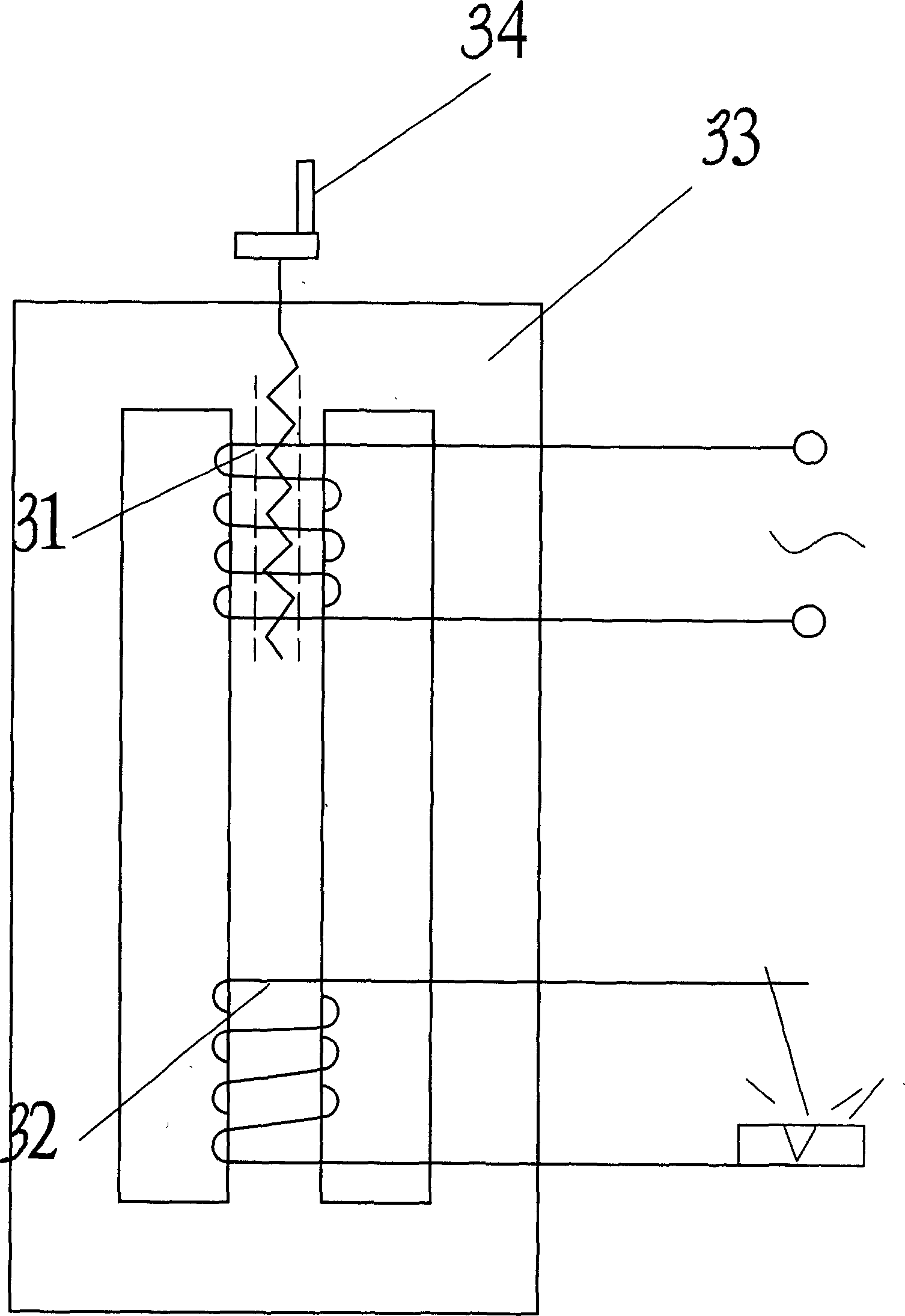
Taking the electric welding machine as an example, the existing AC arc welding machine, if attached Figure 1-3 As shown, they all use the size of the reactance to limit (reduce) the working current of the secondary side, that is, increase the reactance to reduce the current or change the connection method to change the no-load voltage of the secondary side to adjust the secondary side. Working current, its power factor is very low, the existing BX3 series moving coil AC arc welding machine (refer to the attached image 3 ) is only 0.43; BX1 series magnetic shunt moving iron AC arc welding machine (see attached figure 1 ) power factor is 0.48; BX2 series (refer to attached figure 2 ) power factor is 0.62
The existing AC arc welding machine, no matter it is moving iron type or moving coil type, can only adjust the size of welding current by adding reactance, but as long as reactance is added, the power factor will decrease, that is, adding The greater the reactance, the smaller the working current and the lower the power factor. The reactance of these arc welding machines is inversely proportional to the power factor
However, the existing tap-type AC arc welding machine taps from the primary winding to change the size of the secondary no-load voltage to adjust the size of the welding current. The reactance value remains unchanged and the power factor will not be improved.

Method used


Image

  • Method of increasing electric appliance power factor
  • Method of increasing electric appliance power factor
  • Method of increasing electric appliance power factor

Examples


Embodiment Construction

[0042] The present invention will be further described through the embodiments below in conjunction with the accompanying drawings.

[0043] Embodiment of moving coil AC arc welding machine

[0044] Refer to attached Figure 4 The primary static winding 41 and the secondary static winding 42 of the moving coil AC arc welding machine are independently wound on two different iron core columns of the same iron core 49, and the coils of the reactance dynamic winding 43 are collectively wound on the primary and secondary Outside the two windings, the primary and secondary windings are enclosed in the reactance winding at the same time. The reactance winding is an integral winding. The effective turns of the reactance winding coils wound on the core columns of the primary and secondary windings Exactly the same, the magnetic fluxes generated by the reactance windings on two different iron core columns are equal in size and opposite in direction, and the sum of the induced electromo...


PUM


Abstract

This invention relates to an electric welding machine, especially to an energy saving AC machine, in which, the first and second windings of the transformer are winded on two different posts of a core separately, coils of reactance windings wind the posts of a first and second windings, the effective turns of which are complete the same and the fluxes generated by the reactance windings are the same in opposite direction and the sum of the sensed electromotive force generated is zero, that means that the reactance of the winding is used to overcome that of the electric appliances to increase the output current of the secondary winding and power factors of the appliances.

Description

Technical field: [0001] The invention relates to a method for improving the power factor of electrical appliances, in particular to a method for improving the power factor of electrical appliances with coils. Background technique: [0002] At present, electrical products with coils have been widely used in industrial production and people's lives, such as electric welding machines, transformers, motors, etc. The power factor of these products is not high, wasting a lot of precious energy in vain. Taking the electric welding machine as an example, the existing AC arc welding machine, if attached Figure 1-3 As shown, they all use the size of the reactance to limit (reduce) the working current of the secondary side, that is, increase the reactance to reduce the current or change the connection method to change the no-load voltage of the secondary side to adjust the secondary side. Working current, its power factor is very low, the existing BX3 series moving coil AC arc welding...

Claims


Application Information

Patent Timeline
IPC IPC(8): H01F27/28H01F29/02
Inventor 沈淑红吕国兴蒋凤岐蒋凤义蒋敏娟
Owner 蒋风岐
Why Eureka
Try Eureka