
Double-source battery pack switching method and system

A technology for switching systems and battery packs, which is applied in battery/battery traction, battery/fuel cell control devices, charging stations, etc., and can solve problems such as the circulation of dual-source battery packs that is easy to generate

Active Publication Date: 2020-06-05
HUNAN UNIV
View PDF6 Cites 11 Cited by
  • Summary
  • Abstract
  • Description
  • Claims
  • Application Information

AI Technical Summary

Problems solved by technology

[0003] The present invention provides a dual-source battery pack switching method and system to solve the problem that the dual-source battery pack switching is easy to generate circulating current without a DC / DC converter

Method used


Image

  • Double-source battery pack switching method and system
  • Double-source battery pack switching method and system
  • Double-source battery pack switching method and system

Examples


Embodiment 1

[0085] This embodiment provides a dual-source battery pack switching method, including:

[0086] Obtain the first terminal voltage of the currently used battery pack and the second terminal voltage of the battery pack to be switched in real time;

[0087] During normal driving:

[0088] Switching method one, if the difference between the voltage at the first terminal and the voltage at the second terminal is within the first preset range, the battery pack is switched directly;

[0089] If the difference between the voltage at the first terminal and the voltage at the second terminal exceeds the first preset range, it includes:

[0090] Switching method 2, if the voltage at the second terminal is lower than the voltage at the first terminal, adjust the output vectors of the iq axis and the id axis of the vehicle motor, so that the efficiency of the vehicle motor is reduced and the output torque and speed remain unchanged, so that the first terminal of the currently used batter...

Embodiment 2

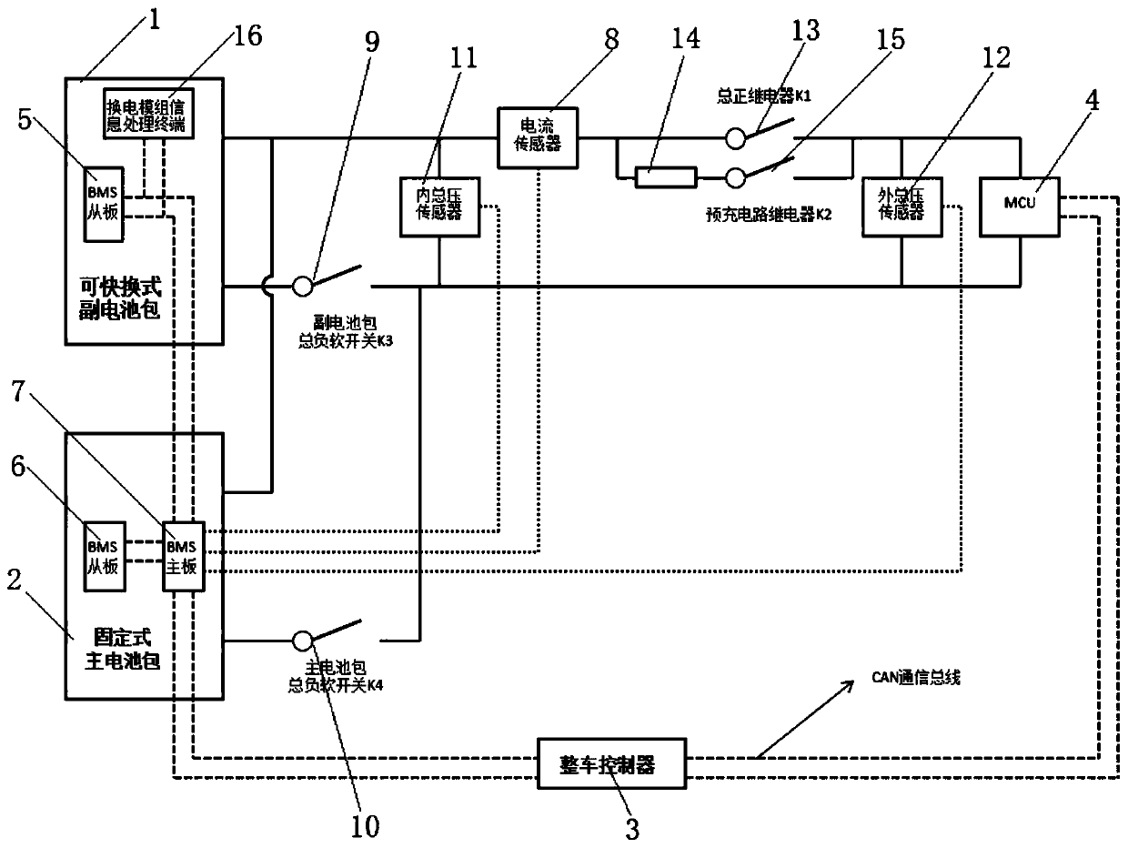
[0118] This embodiment provides a dual-source battery pack switching system, such as figure 1 As shown, it includes a battery information collection module, a vehicle controller 3, a motor controller (MCU) 4, and a switch module, and the battery information collection module, the motor controller 4, and the switch module are all connected to the vehicle controller 3 ;

[0119] The battery information collection module is used to obtain the first terminal voltage of the currently used battery pack and the second terminal voltage of the battery pack to be switched and send them to the vehicle controller 3;

[0120] The vehicle controller 3 is used to perform the following operations:

[0121] During normal driving:

[0122] Switching mode 1, if the difference between the received first terminal voltage and the second terminal voltage is within the first preset range, send an instruction to the switch module to directly switch the battery pack;

[0123] If the difference betwe...


PUM


Abstract

The invention discloses a double-source battery pack switching method and a system. The method comprises the following steps: acquiring a first end voltage of a currently used battery pack and a second end voltage of a to-be-switched battery pack in real time; in the normal driving process, if the difference value between the first end voltage and the second end voltage is within a first preset range, directly performing battery pack switching; otherwise, if the second end voltage is smaller than the first end voltage, adjusting the output vector of the vehicle motor to reduce the first end voltage, and when it is detected that the difference between the reduced first end voltage and the second end voltage is within a first preset range, switching the battery pack; and if the second terminal voltage is greater than the first terminal voltage, reducing the output power of the vehicle motor or controlling the motor to brake, so that the first terminal voltage is increased, and when the difference between the increased first terminal voltage and the second terminal voltage is detected to be within a first preset range, switching the battery pack. Circulation can be avoided or reducedin the battery pack switching process under the condition that a DC / DC converter is not needed.

Description

technical field [0001] The invention relates to the technical field of new energy vehicles, in particular to a dual-source battery pack switching method and system. Background technique [0002] The current dual-source battery pack control and switching technology usually requires a bidirectional DC / DC converter in order to solve the problem of voltage differences between the two battery packs; for example, Chinese patent 2019101086642 discloses a dual-battery pack power supply device and its The control method, including the first battery pack, the second battery pack, a DCDC circuit (equivalent to a DC / DC converter) and a motor controller, needs to rely on the DCDC circuit to adjust the output voltages of the first battery pack and the second battery pack to be consistent to switch. If there is no DC / DC converter, the battery pack is switched directly. When the output voltages of the two battery packs are different, the battery pack with high voltage will charge the batte...

Claims


Application Information

Patent Timeline
Patent Type & Authority Applications(China)
IPC IPC(8): B60L58/12B60L50/60B60L53/80
CPCB60L50/60B60L53/80B60L58/12Y02T10/70Y02T10/7072
Inventor 周维黄鹏陈正欧阳晓平
Owner HUNAN UNIV
Learn More