Manual bisteady-state fast turnover mechanism

A flipping mechanism and bistable technology, applied in the field of manual bistable fast flipping mechanism, can solve the problems of application field limitation and inability to use, and achieve the effects of simple structure, avoiding half-open half-closed state, and reliable operation

Inactive Publication Date: 2006-06-28
王光顺
View PDF1 Cites 5 Cited by
  • Summary
  • Abstract
  • Description
  • Claims
  • Application Information

AI Technical Summary

Problems solved by technology

However, because the mechanism needs to use electric energy, it can only maintain the original state after a power outage, and cannot be used during a power outage, so the application field is limited.

Method used


Image

  • Manual bisteady-state fast turnover mechanism

Examples


Embodiment Construction

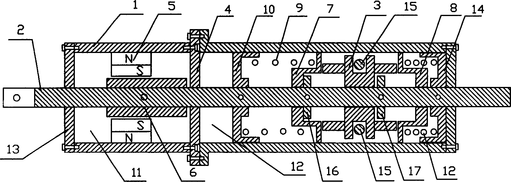
[0014] As shown in the accompanying drawings, the manual bistable quick turning mechanism of the present invention includes a housing 1 and a drive shaft 2 slidably inserted in the housing 1. The housing 1 is cylindrical, with belts at both ends. There is a closed end cover, and there is a partition 4 perpendicular to the drive shaft 2 in the middle of the housing 1. The partition 4 separates the housing 1 into a permanent magnet cavity 11 and a spring cavity 12, and the drive shaft 2 passes through the partition. The board 4 and the end covers on both sides are slidably inserted into the housing 1 . The position in the permanent magnetic chamber 11 on the drive shaft 2 is fixedly equipped with a cylindrical iron core 6, the diameter of the iron core 6 is greater than the drive shaft 2, and the length is less than the width of the permanent magnetic chamber 11, so that it can be moved with the drive shaft 2 The permanent magnet cavity 11 reciprocates; the inner wall of the per...


PUM


Abstract

This invention relates to an artificial bistable quick overturn unit including a shell and a drive shaft movably plugged in the shell, in which, a fork block is set on the shaft and is connected with an artificial fork, a baffle plate is set in the shell vertical to the shaft and separates the shell into a permanent magnetic cavity and a spring cavity, a magnet is fixed on the internal wall of the magnet cavity, a core is mounted on the shaft in the magnet cavity, the fork block can be slidedly bushed on the shaft of the spring cavity, two spring seats are bushed on the shaft of both sides of the block, two push boards are fixed on the shaft of outsides of the spring seat and a spring is set between the seat and the push board.

Description

technical field [0001] The invention relates to a conversion mechanism, in particular to a manual bistable fast turning mechanism. Background technique [0002] The liquid conversion mechanism is used in the power switch hydraulic operating mechanism. When the hydraulic system loses pressure and needs to start the standby device, it is generally operated manually, but the intermediate state of half opening and half closing is easy to occur during manual operation, resulting in opening and closing accidents. My other patent "a permanent magnet switch operating mechanism" (patent number: CN97233462.9) discloses an electric operating mechanism, which makes the operating mechanism stable in two states of separation and closure after the completion of the action, and preferably Solved the movement problem of half-point half-close. However, because the mechanism needs to use electric energy, it can only maintain the original state after a power failure, and cannot be used during...

Claims


Application Information

Patent Timeline
Patent Type & Authority Applications(China)
IPC IPC(8): H01H3/00H01H3/02H01H5/02H01H5/04
Inventor 王光顺
Owner 王光顺
Why Eureka
Try Eureka