Positioning jig for vehicular-part mounting hole
一种车辆定位、安装用的技术,应用在车辆部件、车辆安全安排、用于工件的钻模等方向,能够解决安装作业费时间、安装作业烦杂、作业负担大等问题,达到减轻作业负担、减小空间、缩短作业时间的效果
- Summary
- Abstract
- Description
- Claims
- Application Information
AI Technical Summary
Problems solved by technology
Method used
Image
Examples
no. 2 Embodiment approach
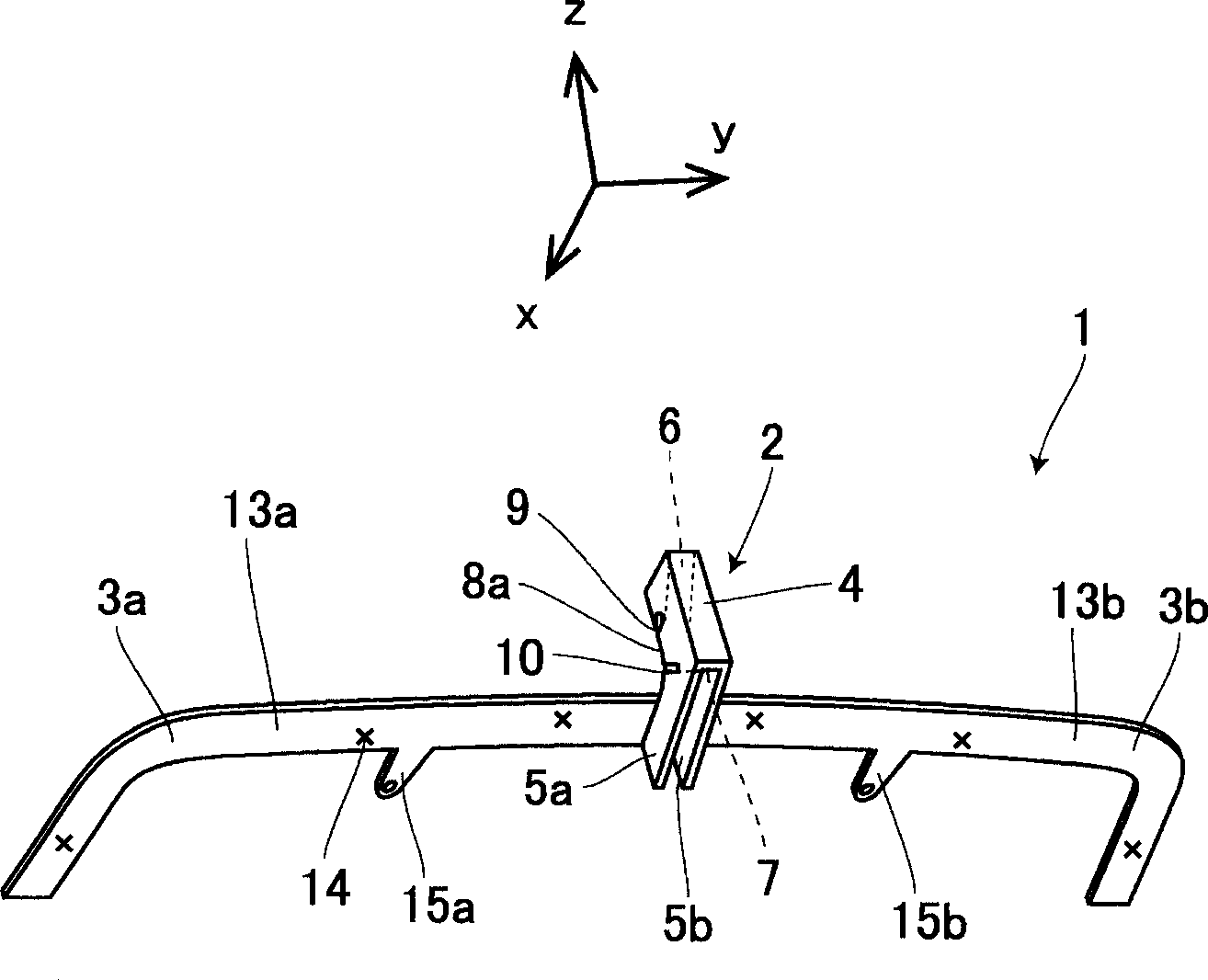
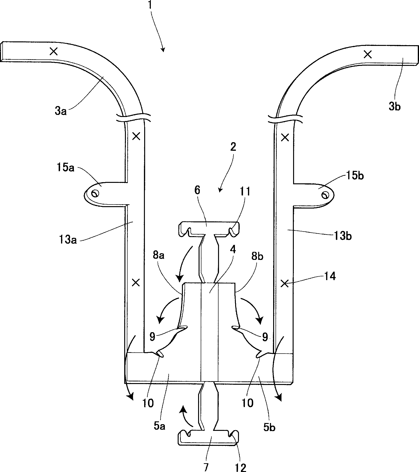
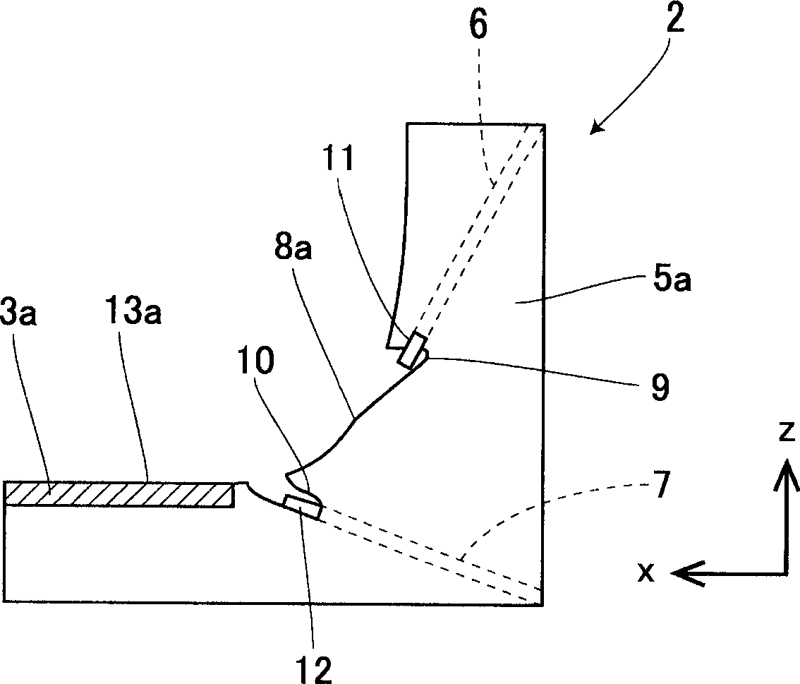
[0072] Figure 7 and Figure 8 in with figure 1 and figure 2 Corresponding parts are marked with the same reference numerals, in Figure 7 and Figure 8 In the figure, the positioning tool 25 for the hole for installing the vehicle component is shown. The positioning tool 25 for the hole for installing the vehicle component is used to penetrate the hole for installing the vehicle component for installing the rear spoiler in the rear fuse of the vehicle. Use when bar 17 is on. The structure of the positioning part 26 of the positioning tool 25 of the positioning tool 25 for mounting the vehicle component and the positions of the first spacer 27 and the second spacer 28 are different from those of the first embodiment. In this case, the overall view of the rear bumper 17 is omitted, and only the portion near the positioning tool 25 of the vehicle component mounting hole will be described.
[0073] The positioning tool 25 for the mounting hole of the vehicle part is assem...
no. 3 Embodiment approach
[0103] Figure 9 and Figure 10 in with Figure 7 and Figure 8 Corresponding parts are marked with the same reference numerals, in Figure 9 and Figure 10 In the figure, the positioning tool 40 for the hole for installing the vehicle component is shown, and the positioning tool 40 for the hole for installing the vehicle component is used to perforate the hole for installing the vehicle component for installing the rear spoiler in the rear bumper of the vehicle. Use when bar 17 is on. In this case, the general view of the rear bumper 17 and the description of overlapping parts will be omitted, and only the part near the positioning tool 40 of the vehicle component mounting hole and the configuration different from the second embodiment will be described.
[0104] In fact, the positioning tool 40 for the mounting hole of the vehicle component is an assembled type, and the configuration of the positioning portion 41 is different from that of the second embodiment, and the ...
no. 7 Embodiment approach
[0173] Figure 16 in with Figure 15 Corresponding parts are marked with the same reference numerals, in Figure 16 In the figure, the positioning tool 80 for the hole for installing the vehicle component is shown. The positioning tool 80 for the hole for installing the vehicle component is used to penetrate the hole for installing the vehicle component for installing the rear spoiler in the tail luggage of the vehicle. Use when case cover 71. The size of the tool main body 81 of the positioning tool 80 for mounting holes for vehicle components is different from that of the sixth embodiment, and the longitudinal dimensions of the extensions 3a and 3b are also different from the sixth embodiment. By positioning the tool main body 81, The extending portions 3a, 3b are positioned near the substantially center of the trunk lid 71 so that the extensions 3a, 3b can be positioned over the entire width direction (arrow y direction) of the trunk lid 71. The method of assembling the ...
PUM
 Abstract
Description
Claims
Application Information
 - R&D
- Intellectual Property
- Life Sciences
- Materials
- Tech Scout
- Unparalleled Data Quality
- Higher Quality Content
- 60% Fewer Hallucinations
Browse by: Latest US Patents, China's latest patents, Technical Efficacy Thesaurus, Application Domain, Technology Topic, Popular Technical Reports.
© 2025 PatSnap. All rights reserved.Legal|Privacy policy|Modern Slavery Act Transparency Statement|Sitemap|About US| Contact US: help@patsnap.com


