Coil rotation positioning device of magnetic resonance imaging equipment

A magnetic resonance imaging and positioning device technology, applied in magnetic resonance measurement, nuclear magnetic resonance analysis, measurement devices, etc., can solve problems such as immovable, unsolvable, and unquantifiable movement

Active Publication Date: 2006-07-12
SIEMENS HEALTHINEERS LTD
View PDF0 Cites 6 Cited by
  • Summary
  • Abstract
  • Description
  • Claims
  • Application Information

AI Technical Summary

Problems solved by technology

[0011] Although as mentioned above, magnetic resonance imaging has the ability to directly slice in any direction, but the direct slice in any direction is only limited to a certain fixed position, so the defect of the magnetic resonance imaging equipment using the above-mentioned head coil is that: when After the part to be inspected is fixed by brackets, cushions, air bags or vacuum bags in the cavity, it cannot move quantitatively in any direction; even if it can be properly moved in the direction perpendicular to the cavity position adjustment, but when the inspection needs to be sliced ​​at other specific positions, such as the position where the part to be inspected is rotated by a specific angle, the magnetic resonance imaging equipment using the above-mentioned head coil cannot meet the above requirements
However, this kind of equipment also cannot solve the problem that the patient's part to be examined cannot be moved after being fixed.

Method used


Image

  • Coil rotation positioning device of magnetic resonance imaging equipment
  • Coil rotation positioning device of magnetic resonance imaging equipment
  • Coil rotation positioning device of magnetic resonance imaging equipment

Examples


Embodiment Construction

[0027] The present invention will be described in detail below in conjunction with the accompanying drawings.

[0028] The rotation positioning device of the magnetic resonance imaging equipment coil of the present invention is arranged on a coil of the magnetic resonance imaging equipment to realize free rotation and precise positioning of the part to be inspected. The present invention can be widely applied to various coils of magnetic resonance imaging equipment. In this preferred embodiment and subsequent embodiments, only the head coil is used as an example, but it is not limited to this, as in the field A person of ordinary skill can understand that devices that are the same as or similar to the rotation positioning device of the magnetic resonance imaging equipment coil of the present invention applied to other coils are all within the scope of the present invention.

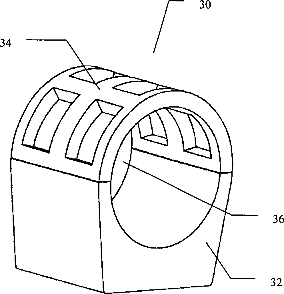
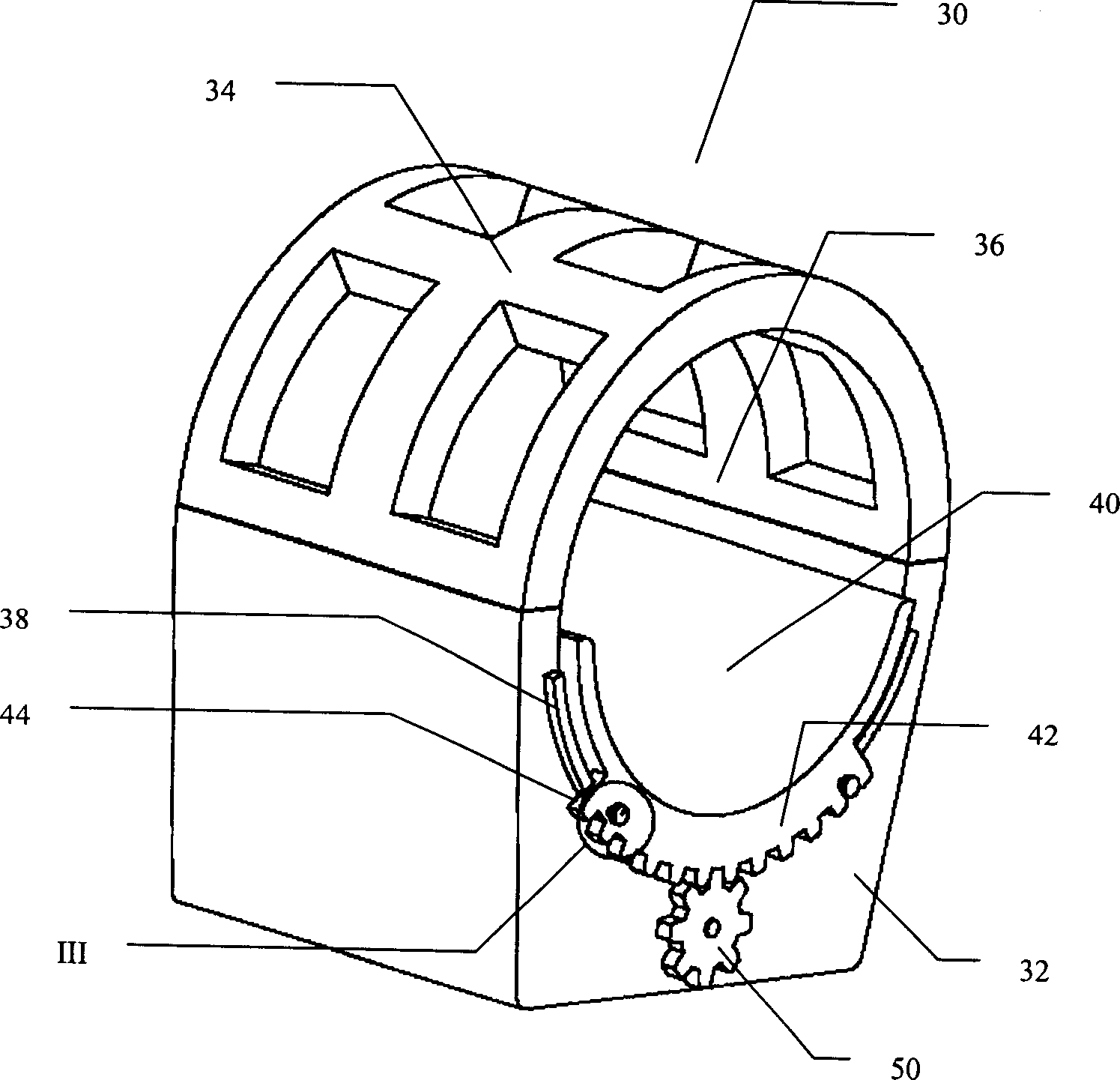
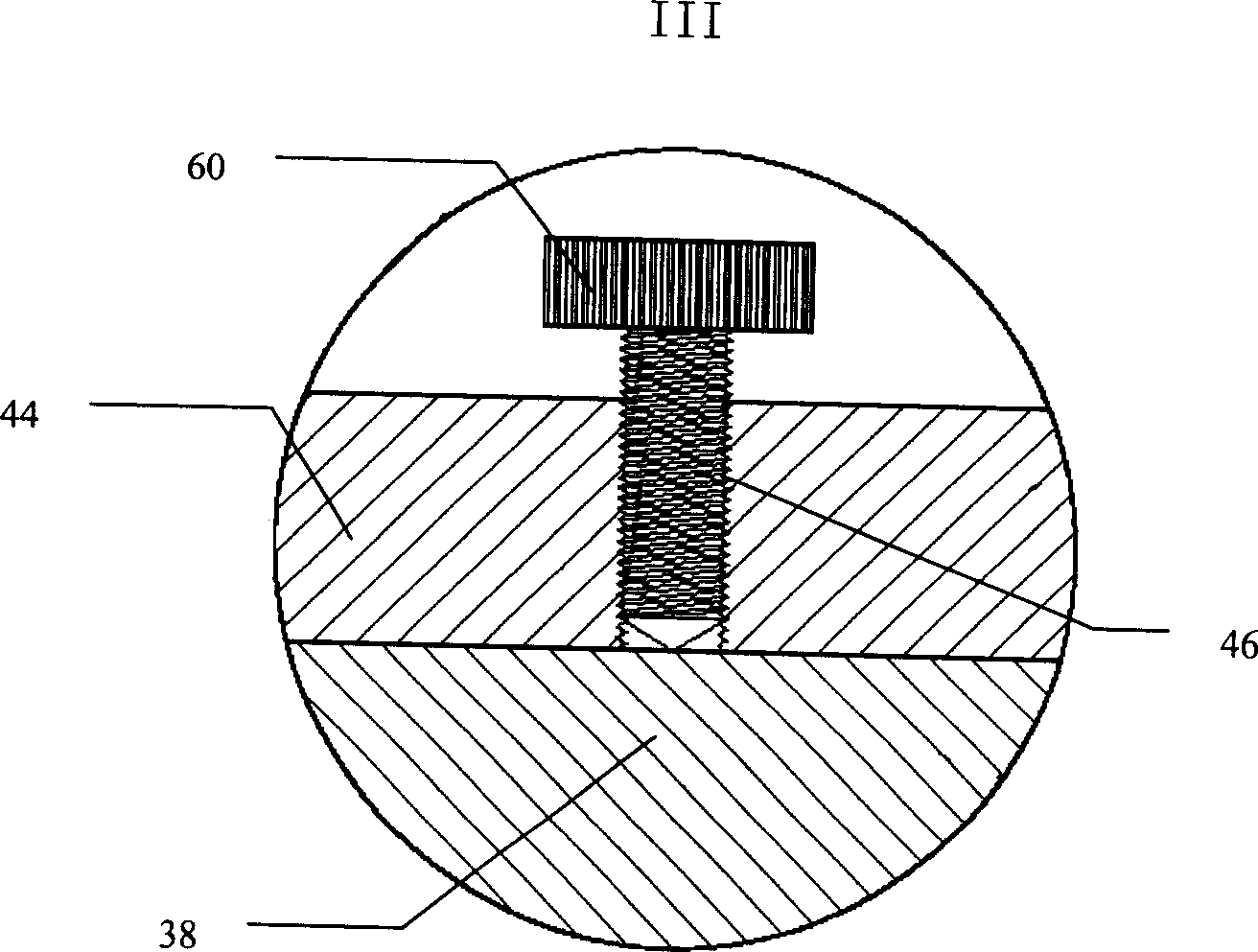
[0029] See figure 2 A head coil 30 includes a base 32 and a top 34, and the top 34 is fixed on the base 3...


PUM


Abstract

The invention provides a rotational locating device applied in the coil of magnetic resonance imaging device, the coil comprising an accommodating cavity for pre-checked component, the said rotational locating device comprising a cushion which can rotate freely in the said accommodating cavity, the cushion is equipped with the first driving component and the first rotating component; while the second driving and rotating component are equipped in coil; the first and second driving component forms the transmission countershaft, the first rotating component rotates relatively with the second rotating device being driven by the first and second driving component, the second driving component is driven artificially or by connecting with external driving source and thus drives the first driving component, through which driving the cushion to rotate through the cooperation of the first and second rotating component, and at the same, controlling the quantitative rotating angle and course of the cushion rotating through rational configuration of the first and second driving component position and size.

Description

(1) Technical field [0001] The invention relates to a positioning device for a magnetic resonance imaging (Magnetic Resonance Imaging; MRI) equipment coil, and more specifically to a rotation positioning device for a magnetic resonance imaging equipment coil. (2) Background technology [0002] Magnetic resonance imaging technology has become an important tool in radiodiagnostic medicine in recent years. Magnetic resonance imaging uses radio frequency (Radio Frequency; RF) as the excitation to observe the magnetic moment change signal of a specific type of atomic nucleus from being disturbed to restoring balance under a strong static magnetic field. The magnetic moment change signal is converted into an electrical signal using Faraday's law, and an image of the original atom density in the object is obtained through a two-dimensional Fourier transform (two dimensional Fourier transform) operation. [0003] The use of magnetic resonance imaging has the following advantages: [0004...

Claims


Application Information

Patent Timeline
Patent Type & Authority Applications(China)
IPC IPC(8): A61B5/055G01R33/20G01N24/08
CPCA61B5/0555G01R33/34046A61B5/055
Inventor 刘克成薛廷强王健
Owner SIEMENS HEALTHINEERS LTD
Why Eureka
Try Eureka