
Hydraulic shears

A shearing and hydraulic technology, applied in shearing devices, shearing equipment, underwater operation equipment, etc., can solve the problems of endangering the safety of unmanned remote control submersibles, continuous cutting of wire ropes, inconvenient replacement, etc., achieving light weight, The effect of reducing machining accuracy and working safety and reliability

Inactive Publication Date: 2006-07-12
SHENYANG INST OF AUTOMATION - CHINESE ACAD OF SCI
View PDF0 Cites 17 Cited by
  • Summary
  • Abstract
  • Description
  • Claims
  • Application Information

AI Technical Summary

Problems solved by technology

If the gap is slightly larger or the edge of the cutting knife is damaged, the wire rope will be cut continuously. In severe cases, the movable knife and the fixed knife cannot be disengaged due to the residual steel wire sandwiched between the two blades, which will endanger the safety of the unmanned remote control submersible.
In addition, the fixed knife is connected to the shear head through multiple bolts, which is inconvenient to replace after damage

Method used


Image

  • Hydraulic shears
  • Hydraulic shears

Examples


Embodiment Construction

[0013] The present invention will be described in further detail below in conjunction with the accompanying drawings and embodiments.

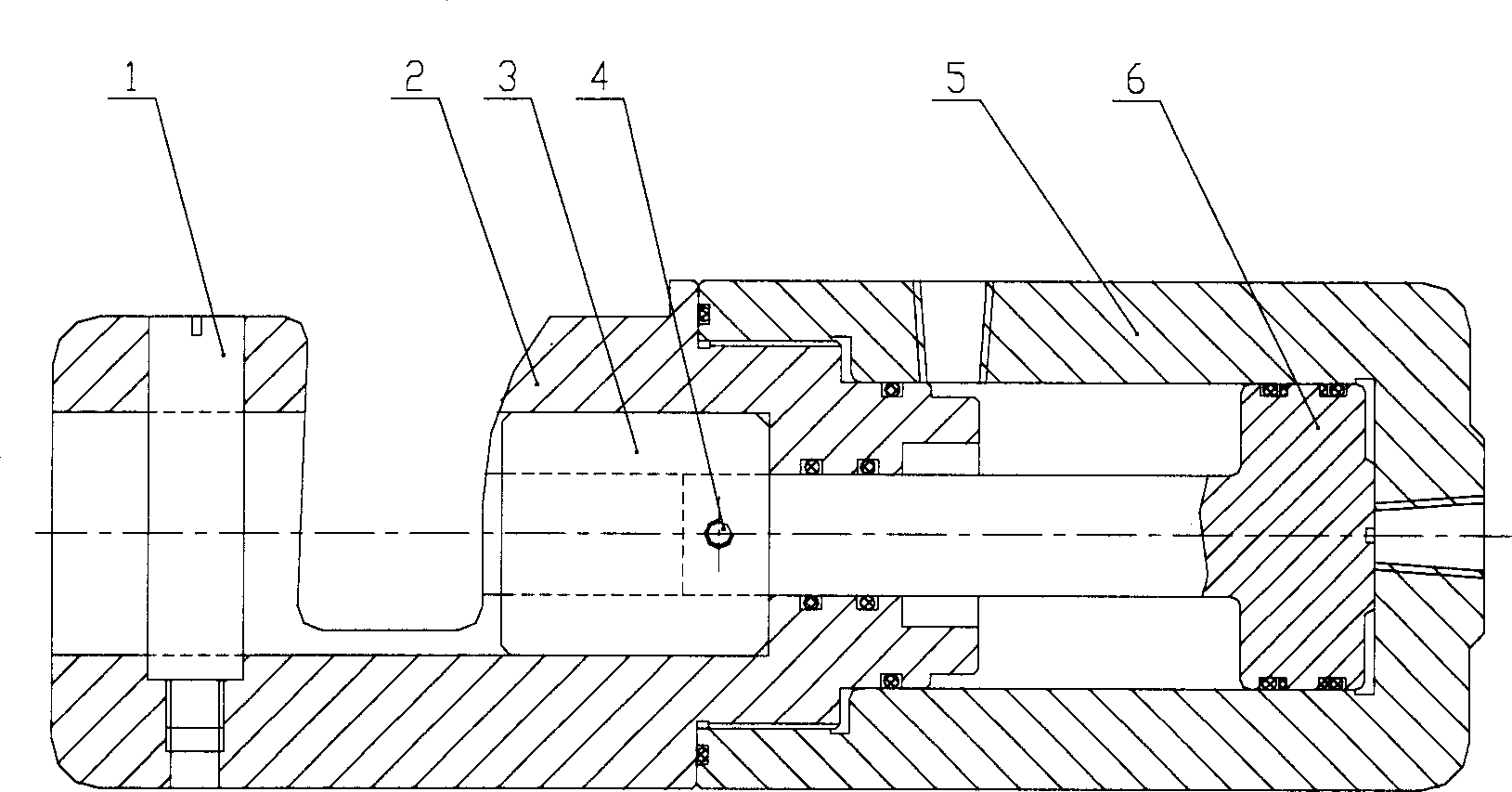
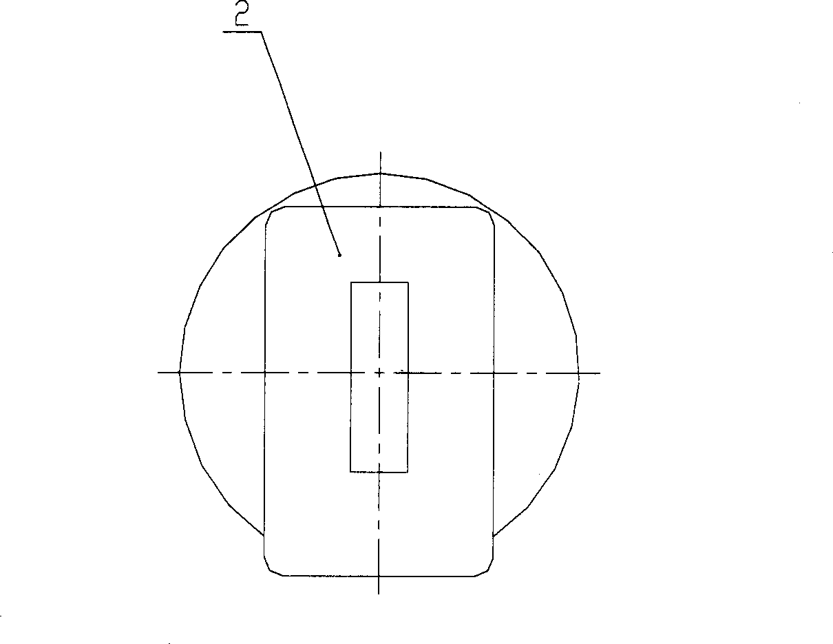
[0014] Such as figure 1 , 2 As shown, the hydraulic shearer of the present invention is structurally mainly composed of a fixed anvil pin 1, a shear head 2, a cutting knife 3, a pull-back cylindrical pin 4, a cylinder body 5, and a piston rod 6, wherein: the shear head 2 is U-shaped One side of the U-shaped structure is a rectangular structure, and there is a grooved guide rail in its horizontal direction (when the cutting knife 3 is placed through the grooved guide rail, the cutting knife 3 is placed in the cavity on the other side of the U shape of the shearing head 2 body structure), there is a cylindrical hole in the vertical direction, and the fixed anvil pin 1 passes through the cylindrical hole and is connected to the U-shaped bottom edge through threads; the other side of the U-shaped is a cylindrical structure, which is connected to ...


PUM


Abstract

The invention relates to underwater robot technique, especially providing a hydraulic-shears, which is formed by a fixing anvil pin, a shearer, a movable shearing cutter, a drawing straight pin, a cylinder, and a piston rod. Wherein, said shearer is in U-shape whose one side is rectangle; the shearer has a horizontal groove guide rail and a cylinder hole at vertical direction; the fixing anvil pin through said cylinder hole is connected to the U-shape bottom edge; another side of U-shape is in post-structure connected with said cylinder; the inner part of post-structure is in chamber structure while a square hole is near the cylinder; the cutter has a groove guide rail through said horizontal direction mounted inside the chamber, to be through said square hole and connected with one end of piston rod via drawing straight pin; and the open of said U-shape structure of said shearer contains steel wire. The invention has simple structure, lower machining precision, non-cutting left of steel wire, smaller size, lighter weight, application of easily changing vulnerable parts, reliable operation and the application of operation unmanned remote-control diving apparatus.

Description

technical field [0001] The invention relates to underwater robot technology, in particular to a hydraulic shearer. Background technique [0002] At present, with the increase of the operating water depth and the increasing difficulty of the operation, the operating unmanned remote control submersible plays an increasingly important role in marine engineering. The operational unmanned remote control submersible completes various underwater operations through the underwater tools it carries. The hydraulic cutter is a representative of linear motion underwater tools. It is installed on the front chassis of the submersible or the underwater manipulator, powered by the hydraulic oil source of the submersible, and used to cut various underwater cables and wire ropes. The working principle of the shear is to generate enough thrust with the help of the power drive system to push the shear blade to move to cut various underwater wire ropes. The ability of the cutter to cut the wire...

Claims


Application Information

Patent Timeline
Patent Type & Authority Applications(China)
IPC IPC(8): B23D15/14B63C11/52
Inventor 张将王棣堂
Owner SHENYANG INST OF AUTOMATION - CHINESE ACAD OF SCI
Learn More