Groove valve

The technology of a valve body and a tubular valve is applied in the field of wine filling devices on a wine production line, which can solve the problems of easy leakage and inconvenient opening.

Inactive Publication Date: 2006-07-12
方建生
View PDF0 Cites 0 Cited by
  • Summary
  • Abstract
  • Description
  • Claims
  • Application Information

AI Technical Summary

Problems solved by technology

[0002] At present, there is no special wine injection device on the wine tank of the domestic wine production line, but an injection port and a cover plate are set on the pipeline of the conveying medium, which are connected by threads or flanges. It is inconvenient to open when injecting wine, and it is easy to leak.

Method used


Image

  • Groove valve
  • Groove valve

Examples


Embodiment Construction

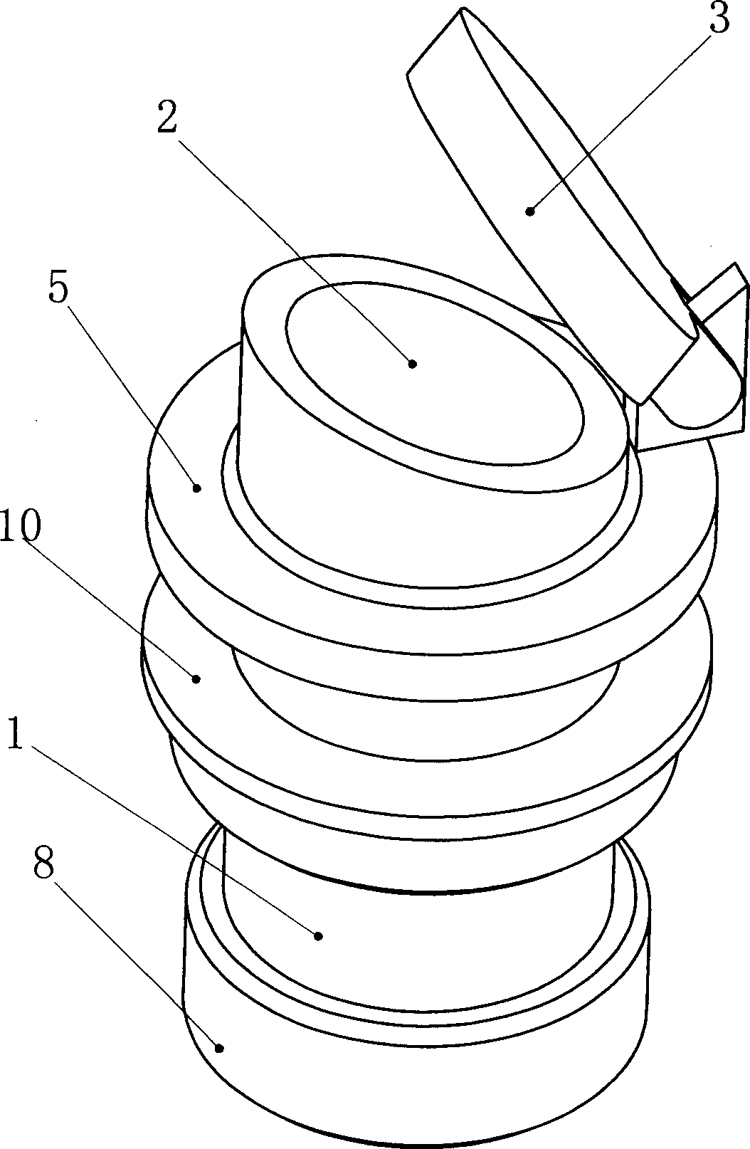
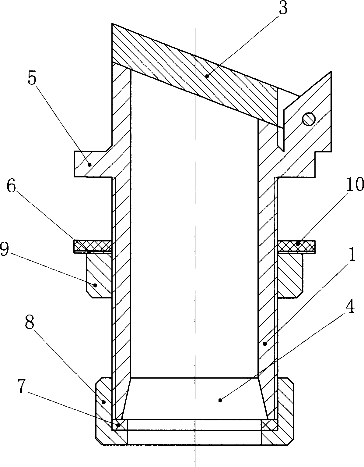
[0011] Such as figure 1 , figure 2 As shown: the valve body 1 of the groove valve is in the shape of a straight pipe, the upper end of the valve body 1 is the injection port 2, the lower end of the valve body 1 is the connection port 4, the end surface of the valve body 1 injection port 2 intersects the axis of the valve body 1 obliquely, and the injection port 2 The end face generally intersects the axis of the valve body 1 at 15° to 30°. The middle part of the outer wall of the valve body 1 is provided with a protruding annular step 5. In this specific embodiment, the annular step 5 is formed by annular ribs. In the vicinity of the lower edge of the injection port 2, the valve cover 3 is hinged on the annular step 5 near the lower edge of the injection port 2. The inclination angle of the valve cover 3 is the same as that of the injection port 2. The inner hole of the connection port 4 is a horn-shaped conical surface with a taper Between 10° and 20°, the end surface of th...


PUM


Abstract

The invention relates to a groove valve which can be used as a wine-filling device in the production lines of Tokay and other wines. The groove valve has a pipe valve (1) whose upper end is the inlet (2); the inlet (2) has a valve cover (3) hinged on the valve (1); the lower end of valve (1) is the interface (4); the middle part of outer wall of valve (1) has a protruded annular step (5), from which to the end of interface (4) is a external screw thread, a sealing ring (10), a cushion ring (6) and a nut (9); the end of interface (4) has a sealing ring (7) and a locked screw cap (8) matching the external screw thread. The invention can avoid leakage with easy opening.

Description

technical field [0001] The invention relates to a trough valve, which is a wine injecting device used in a wine production line, and is also suitable for production lines in beverage and other brewing industries. Background technique [0002] At present, there is no special wine injection device on the wine tank of the domestic wine production line, but an injection port and a cover plate are set on the pipeline of the conveying medium, which are connected by threads or flanges. It is inconvenient to open when injecting wine, and it is easy to leak. Therefore it is very necessary to install a valve cover that is easy to open when pouring wine on the wine tank wall of the production line, and does not allow a tank valve to leak. Contents of the invention [0003] The object of the present invention is to provide a groove valve that is easy to open and disassemble and can meet the sealing function requirements after closing to overcome the deficiencies of the prior art. [...

Claims


Application Information

Patent Timeline
Patent Type & Authority Applications(China)
IPC IPC(8): F16K1/20F16K27/02
Inventor 方建生
Owner 方建生
Why Eureka
Try Eureka