Mechanical seal structure for narrow seal chamber

A technology of mechanical seal device and seal cavity, which is applied in the field of mechanical seal device of pumps, can solve the problems of fast wear of seal surface, frequent replacement, short seal life, etc., achieve balanced and stable elastic compensation, simple and compact structure, axial small size effect

Active Publication Date: 2015-07-15
DONGGUAN HUAHUI PRECISION MASCH CO LTD
View PDF8 Cites 0 Cited by
  • Summary
  • Abstract
  • Description
  • Claims
  • Application Information

AI Technical Summary

Problems solved by technology

[0002] In the centrifugal pump, a considerable part of the radial space of the seal cavity is very narrow, especially when the inner diameter space from the seal shaft to the seal cavity is less than 10mm, the mechanical seal design It brings great difficulty. At present, most of them are designed as non-assembled single-spring unbalanced mechanical seals. During installation, it is necessary to manually adjust the large spring compression, which is extremely inconvenient to operate; when the pressure of the sealing cavity exceeds 10kgf / cm2 or the pressure fluctuates , the liquid film on the end face of this type of seal is unstable, the seal face wears too fast, and the seal life is short
Domestic seal suppliers mostly provide the aforementioned non-packaged spring seals, the transmission of the rotary seals is easy to loose, the price is low, but the service life of the seal is short, and the replacement is frequent; foreign seal suppliers (such as Flowserve Fluid) have launched a series for Mechanical seal with narrow sealing cavity, but the structure is cumbersome, the requirements for sealing material and machining precision are very high, and the price is expensive; in addition, the general welded metal bellows seal has a large radial dimension of the wave plate, mostly 7-10mm, Cannot fit into narrow sealed chambers

Method used


Image

  • Mechanical seal structure for narrow seal chamber
  • Mechanical seal structure for narrow seal chamber
  • Mechanical seal structure for narrow seal chamber

Examples


Embodiment Construction

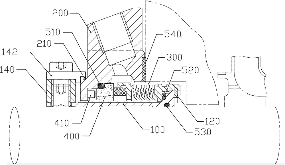
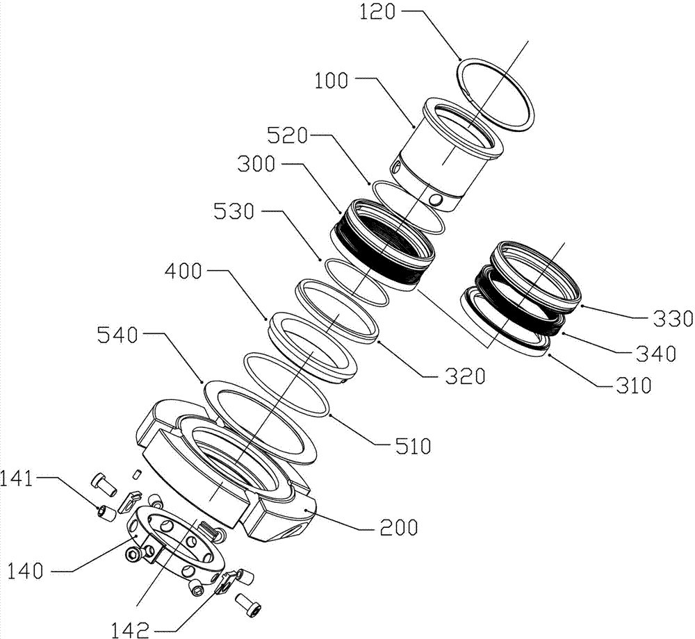
[0019] refer to figure 1 and figure 2 , a mechanical seal device for a narrow sealing cavity, including a shaft sleeve 100, a sealing gland 200, a moving ring assembly 300, a stationary ring 400 and an auxiliary seal.

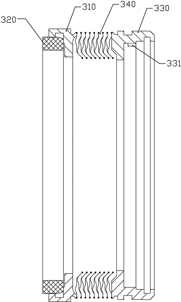
[0020] refer to image 3 The moving ring assembly 300 includes a ring base 310 , a moving ring 320 embedded in the ring base 310 , a base ring 330 , and a welded bellows 340 whose two ends are hermetically connected to the ring base 310 and the base ring 330 . The moving ring assembly 300 is a welded bellows assembly type, which can be used in modules. Compared with the single spring structure, the elastic compensation is balanced and stable; and the moving ring assembly 300 is axially flattened, with a small radial dimension, and is suitable for sealing shafts to A structure with insufficient inner diameter space at the seal cavity.

[0021] refer to Figure 4 The welded bellows 340 includes a protruding piece 341 and a concave piece 342, both of which ar...


PUM


Abstract

The invention discloses a mechanical seal structure for a narrow seal chamber. A dynamic ring assembly of the device comprises a ring seat, a dynamic ring, a base ring and a welded corrugated pipe, wherein the dynamic ring and the base ring are embedded on the ring seat; the welded corrugated pipe is welded between the ring seat and the base ring; a boss is arranged on the external wall of the right end of a shaft sleeve; a sunken part is formed on the left end of the boss; an internal sunken platform with a bulge is arranged at the right end of the base ring; the bulge is engaged with the sunken part, so that the base ring can be linked with the shaft sleeve; a clamp spring propped against the right end of the shaft sleeve is arranged at the right end of the base ring; a static ring is arranged on the internal wall of the seal gland by a hinge pin; a transmission ring is arranged at the left end of the shaft sleeve in a sleeving way; the transmission ring and the shaft sleeve are fixed on a pump shaft by bolts; a plurality of F-shaped positioning blocks are uniformly distributed on the sidewall of the transmission ring; an annular groove is formed on the left end of the sealing gland; and one end of each positioning block is fixed on the sidewall of the transmission ring while the other end of each positioning block is blocked into the annular groove, so that the sealing gland and the transmission ring can be axially fixed and rotated relative to each other; and the sealing gland, the shaft sleeve, the dynamic ring assembly and the static ring form an integrated structure.

Description

technical field [0001] The invention relates to a mechanical sealing device of a pump, in particular to a mechanical sealing device for a narrow sealing cavity. Background technique [0002] In centrifugal pumps, a considerable part of the radial space of the seal chamber is very narrow, especially when the inner diameter space from the seal shaft to the seal chamber is less than 10mm, which brings great difficulty to the design of the mechanical seal. At present, most of them are designed as non-assembled single springs. Type unbalanced mechanical seal, it is necessary to manually adjust the large spring compression during installation, and the operation is extremely inconvenient; when the pressure of the sealing cavity exceeds 10kgf / cm2 or the pressure fluctuates, the liquid film on the sealing end face of this type is unstable, and the sealing surface wears out too quickly , The seal life is short. Domestic seal suppliers mostly provide the aforementioned non-packaged sp...

Claims


Application Information

Patent Timeline
Patent Type & Authority Patents(China)
IPC IPC(8): F04D29/12F04D29/10
Inventor 郭文德
Owner DONGGUAN HUAHUI PRECISION MASCH CO LTD
Why Eureka
Try Eureka