Gas cell sealing method

a gas cell and sealing technology, applied in the direction of magneto-optic devices, instruments, manufacturing tools, etc., can solve the problems that the sealing precision cannot be achieved with these techniques, and the bonding heat applied to the sealant may put a thermal load on the gas cell or on the gas inside the gas cell, so as to improve the sealing precision and improve the sealing precision

Inactive Publication Date: 2018-12-04
SEIKO EPSON CORP
View PDF13 Cites 0 Cited by
  • Summary
  • Abstract
  • Description
  • Claims
  • Application Information

AI Technical Summary

Benefits of technology

[0006]An advantage of some aspects of the invention is to improve the sealing precision of gas cells without having a thermal load applied to the gas cell main body or to the gas inside gas cells.
[0007]An aspect of the invention provides a method for sealing a gas cell. The method is for sealing an opening of the gas cell, and includes: converging a laser beam with a laser beam-converging optical element to a sealant that bonds the gas cell to a lid used to seal the opening; and bonding the gas cell and the lid to each other by applying pressure in a direction that presses the lid and the gas cell. The sealing method enables improving the gas cell sealing precision without having a thermal load applied to the gas cell main body or to the gas inside the gas cell.
[0009]In another preferred aspect of the invention, the load point of the applied pressure occurs within the opening. According to the method for sealing a gas cell, pressure can be more evenly applied to the lid than when the load point does not occur within the opening, and the sealing precision can improve.
[0010]In still another preferred aspect of the invention, the gas cell and the lid are bonded to each other in a vacuum state. According to the method for sealing a gas cell, the vacuum sealing improves the gas cell sealing precision.

Problems solved by technology

In sealing a gas cell by bonding the gas cell main body and a lid with a sealant, the bonding heat applied to the sealant may put a thermal load on the gas cell or on the gas inside the gas cell.
While this enables sealing a wide area, high-precision sealing of a minute area cannot be achieved with these techniques.

Method used


Image

  • Gas cell sealing method
  • Gas cell sealing method
  • Gas cell sealing method

Examples


first embodiment

1. First Embodiment

(1) Configuration

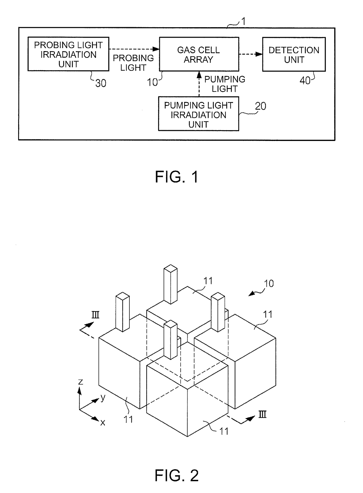
[0022]FIG. 1 is a block diagram representing a configuration of a magnetic measurement device 1 according an embodiment. The magnetic measurement device 1 is a biometric device that measures biological conditions based on a measured index obtained by measuring magnetic fields produced by an organism, for example, such as a magnetic field produced by the heart (cardiac magnetic field) or the brain (cerebral magnetic field). The magnetic measurement device 1 includes a gas cell array 10, a pumping light irradiation unit 20, a probing light irradiation unit 30, and a detection unit 40. The gas cell array 10 has a plurality of gas cells. Each gas cell is filled with an alkali metal gas (for example, cesium (Cs)). The pumping light irradiation unit 20 outputs pumping light that interacts with the alkali metal atoms (for example, light of 894 nm wavelength corresponding to the D1 line of cesium. The pumping light has a circularly polarized light compone...

second embodiment

2. Second Embodiment

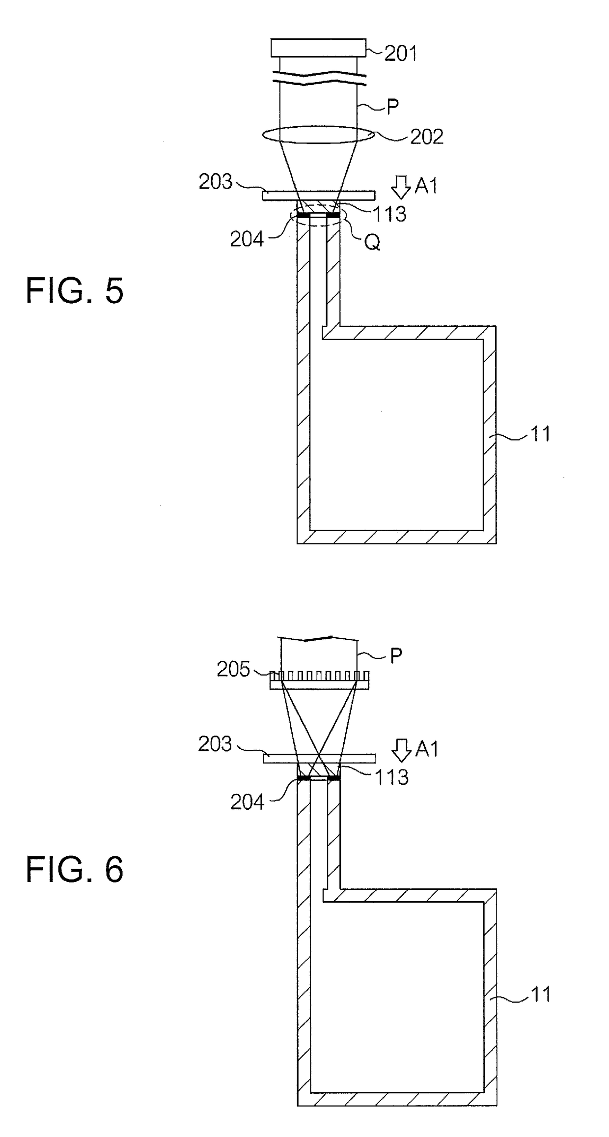
[0041]FIG. 6 is a diagram representing a method for sealing the gas cells 11 according to Second Embodiment. In contrast to First Embodiment in which the lens 202 is used as the optical element that converges a laser beam, Second Embodiment uses an optical element 205 in place of the lens 202. The optical element 205 is an optical element that controls a laser beam for more efficient and selective irradiation than in First Embodiment. The optical element 205 forms a beam intensity distribution of a shape that conforms to the disposition of the sealant 204. For example, when the sealant 204 is disposed in a ring-like fashion around the opening, the optical element 205 controls the beam intensity distribution in such a way as to conform to the ring-like disposition of the sealant.

[0042]The optical element 205 has a converging function to converge a laser beam, and a ring-forming function to form a ring-like laser beam intensity distribution. Here, the specific phas...

third embodiment

3. Third Embodiment

[0045]FIG. 7 is a diagram representing a method for sealing the gas cells 11 according to Third Embodiment, analogous to FIG. 5 of First Embodiment. In First Embodiment, the lens 202 (optical element) and the pressurization substrate 203 are configured as separate members. In contrast, Third Embodiment uses a pressurization substrate 206 provided as an integral unit of an optical element and a pressurization substrate. An optical element (for example, diffraction grating) that controls a laser beam is disposed on the surface 206a of the pressurization substrate 206. The pressurization substrate 206 is pressed against the lid 113 on the surface 206b opposite the surface 206a.

[0046]In this embodiment, aberration and other such effects can be reduced by the provision of the integrally provided optical element and pressurization substrate, and a laser beam can be irradiated even more efficiency and selectively.


PUM

PropertyMeasurementUnit
temperatureaaaaaaaaaa
widthaaaaaaaaaa
transparentaaaaaaaaaa

Abstract

A gas cell sealing method includes bonding step in which a bonding portion of a gas cell main body having an opening and a lid for closing the opening where a sealant for bonding the gas cell main body and the lid is provided is heated by converging a laser beam from a laser light source through an optical element, and the lid is bonded to the gas cell main body by applying pressure in a direction that presses the lid against the gas cell main body, the pressure being applied while the laser beam is being converged to the bonding portion.

Description

BACKGROUND[0001]1. Technical Field[0002]The present invention relates to a gas cell sealing method.[0003]2. Related Art[0004]Techniques are known that seal an electronic component package or a semiconductor package. For example, JP-A-2002-137939 describes melting a sealing member under a predetermined temperature distribution created on a glass member surface by forming an irradiation power distribution with optical heating means. Japanese Patent No. 4665260 describes a glass substrate sealing system that includes a laser process assembly that forms an airtight sealing portion by heat melting a sealing material disposed along a plurality of display packages disposed between glass substrates, a transfer assembly that supplies glass substrates to a work table disposed underneath the laser process assembly, and a buffer assembly that retains glass substrates in a manner allowing glass substrates to be continuously supplied to the work table via the transfer assembly. The work table has...

Claims


Application Information

Patent Timeline
Patent Type & Authority Patents(United States)
IPC IPC(8): B29C65/16G01R33/032G01R33/00B23K26/06B23K26/20B23K26/324B23K103/00
CPCG01R33/032B23K26/0648B23K26/0652B23K26/324G01R33/0052B23K26/206B23K2103/54
Inventor FUJII, EIICHINAGASAKA, KIMIO
Owner SEIKO EPSON CORP
Why Eureka
Try Eureka