Raymond mill device
A grinding device and Raymond machine technology, applied in the field of Raymond machines, can solve the problems of reducing the working efficiency and processing quality of Raymond mills, and the small grinding force, so as to improve the grinding fineness and grinding efficiency, improve the service life, and improve the The effect of line speed
- Summary
- Abstract
- Description
- Claims
- Application Information
AI Technical Summary
Problems solved by technology
Method used
Image
Examples
Embodiment 1
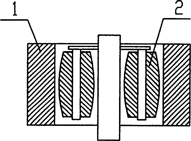
[0016] Embodiment one: if figure 1 As shown, the Raymond machine grinding device includes a grinding ring 1 and at least two grinding rollers 2 uniformly distributed circumferentially along the axis of the grinding ring 1. The grinding rollers 2 are in the shape of a drum with a large middle and small ends. The internal cavity of 1 is a common cylindrical shape. This structure makes the grinding roller have a certain amount of pre-wear, thus improving the service life of the grinding roller.
Embodiment 2
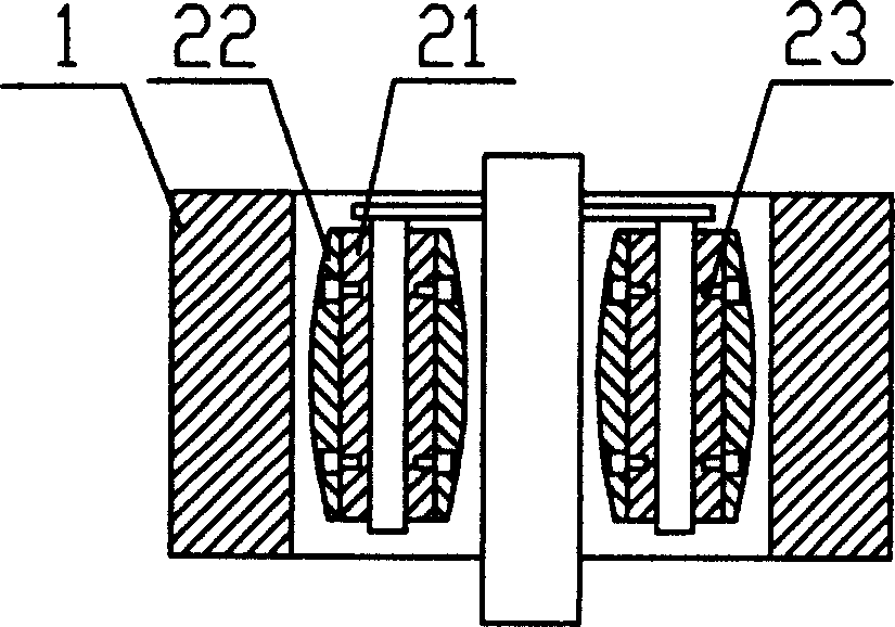
[0017] Embodiment two: if figure 2 As shown, this embodiment is basically the same as Embodiment 1, the difference is that the drum-shaped grinding roller 2 is a split structure, including a middle roller body 21, and a drum-shaped outer surface sleeved on the middle roller body 21 The grinding sleeve 22 is provided with a fastening device 23 between the intermediate roller body 21 and the grinding sleeve 22; the fastening device 23 can adopt a conventional fastening method, such as bolt connection; the intermediate roller body 21 and the grinding sleeve 22 The cross section of the joint part can be circular or square.
Embodiment 3
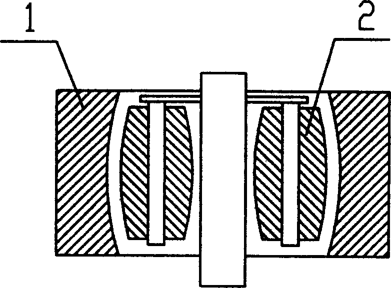
[0018] Embodiment three: as image 3 As shown, the Raymond machine grinding device includes a grinding ring 1 and at least two grinding rollers 2 uniformly distributed circumferentially along the axis of the grinding ring 1, and the grinding rollers 2 are drum-shaped with a large middle and small ends; the grinding ring The inner cavity of 1 is the drum-shaped cavity corresponding to the drum-shaped grinding roller 2. In addition to the advantages of the first embodiment, this structure increases the contact area between the material, the grinding roller and the grinding ring, and improves the grinding opportunity. During the use of ordinary Raymond mills, the grinding roller 2 wears first, and then the grinding ring wears into a drum-shaped cavity. In this case, the use of the grinding roller of the present invention can prolong the service life of the grinding ring and reduce production costs , this structure is also within the protection scope of the present invention.
PUM
 Abstract
Description
Claims
Application Information
 - R&D
- Intellectual Property
- Life Sciences
- Materials
- Tech Scout
- Unparalleled Data Quality
- Higher Quality Content
- 60% Fewer Hallucinations
Browse by: Latest US Patents, China's latest patents, Technical Efficacy Thesaurus, Application Domain, Technology Topic, Popular Technical Reports.
© 2025 PatSnap. All rights reserved.Legal|Privacy policy|Modern Slavery Act Transparency Statement|Sitemap|About US| Contact US: help@patsnap.com


