Servo drive device of lockstitch sewing machine

A technology of a servo drive device and a lockstitch sewing machine, which is applied in the field of sewing machines, can solve the problems that affect the torque and noise performance of the whole sewing machine, the difficulty of parts processing and assembly, and the high production cost, so as to omit the bevel gear transmission structure and facilitate the processing of parts. , the effect of simple structure

Active Publication Date: 2006-07-19
JACK SEWING MASCH CO LTD
View PDF0 Cites 2 Cited by
  • Summary
  • Abstract
  • Description
  • Claims
  • Application Information

AI Technical Summary

Problems solved by technology

Since the sewing machine is a high-precision assembly, the precision requirements for the bevel gear are also high. In addition, a vertical shaft hole is required on the casing to support the vertical shaft to realize the connection and movemen

Method used


Image

  • Servo drive device of lockstitch sewing machine
  • Servo drive device of lockstitch sewing machine
  • Servo drive device of lockstitch sewing machine

Examples


Embodiment Construction

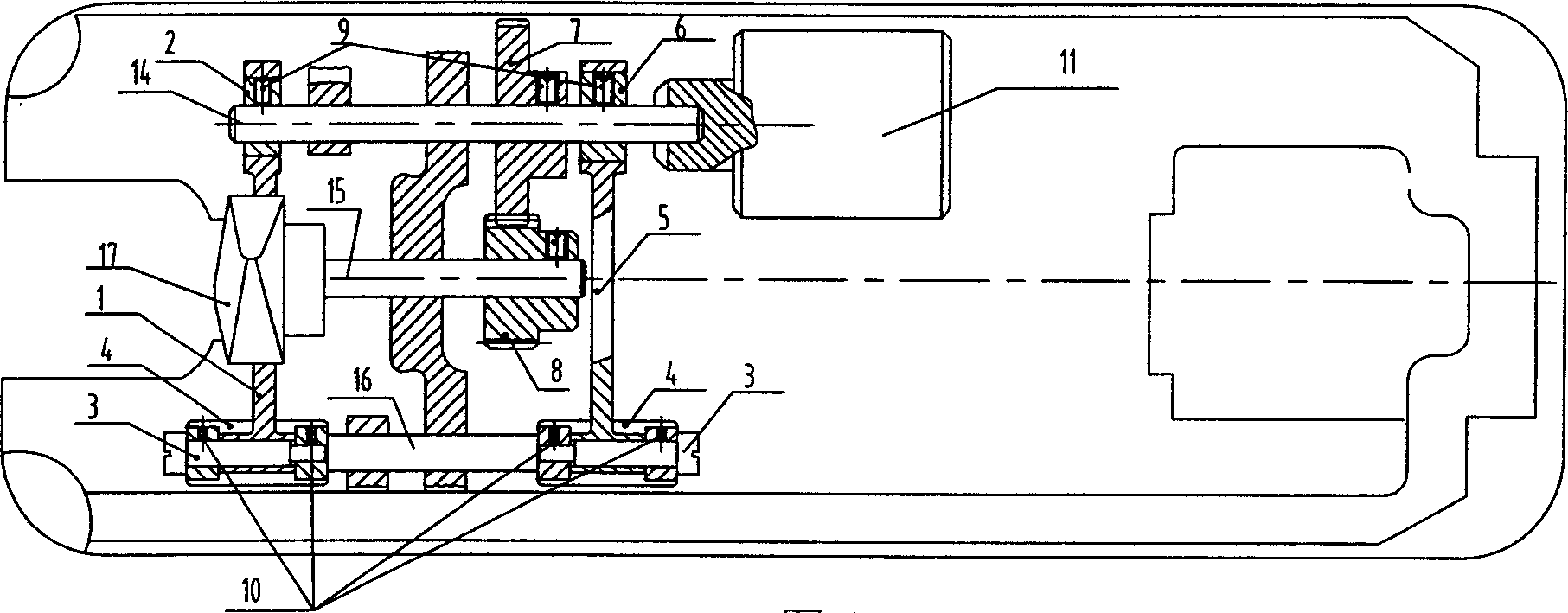
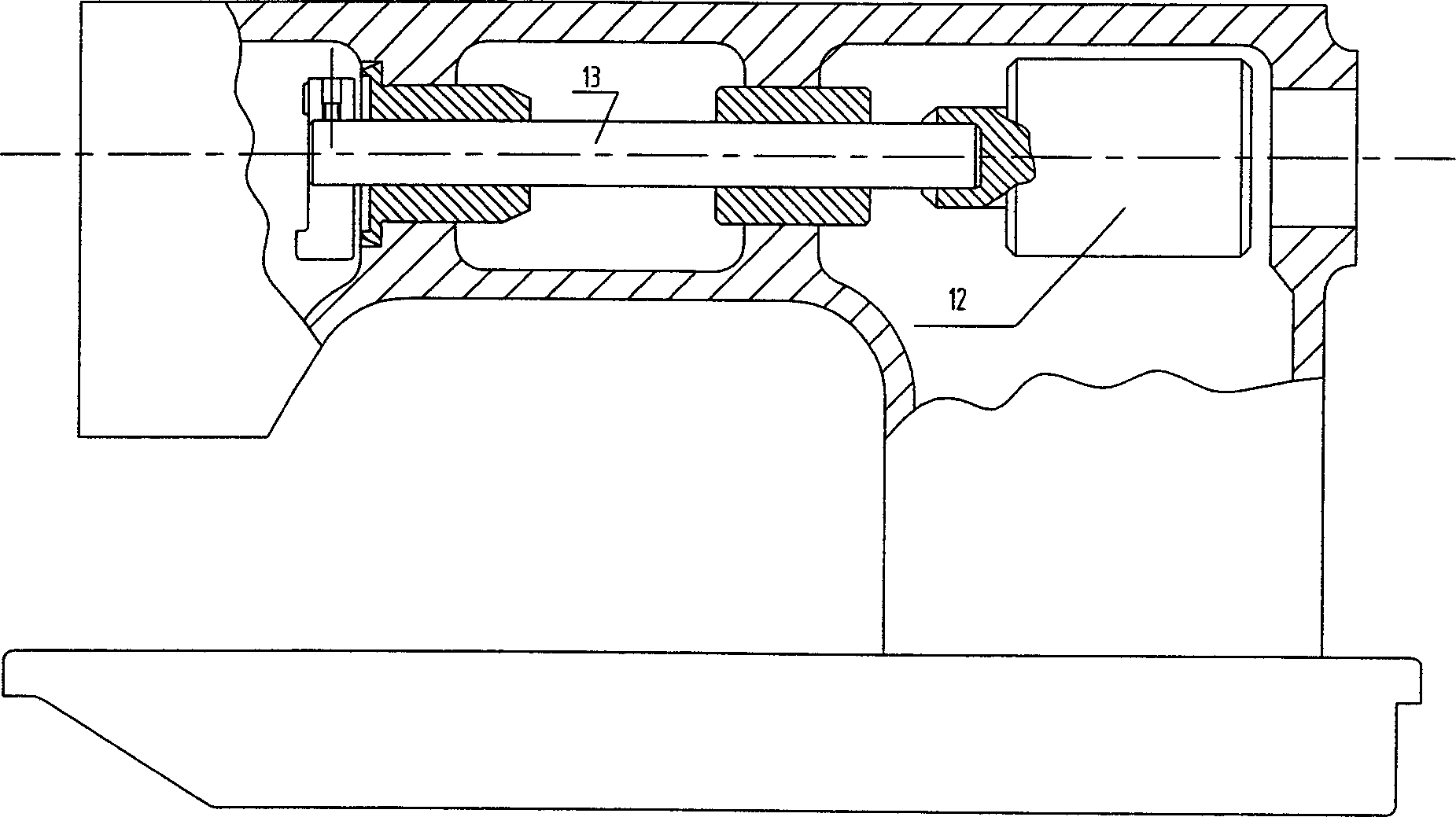
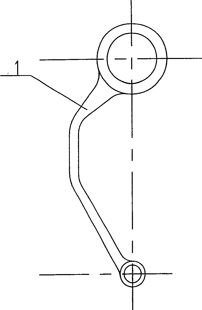
[0014] refer to figure 1 , figure 2 , The upper shaft 13 of the lockstitch machine is directly driven by the servo motor 12 and rotates; the tooth lifting shaft 14 is directly driven by the servo motor 11 and rotates. The right end of the lifting tooth shaft 14 is equipped with a feeding cam 6 and fixed with a set screw 9. The two ends of the feeding shaft 16 are respectively covered with a sleeve 4 and fixed by a set screw 10. The upper end of the feeding connecting rod 5 is sleeved on the feeding cam 6, and the lower end The pin shaft 3 is connected to the sleeve 4, so that the rotation of the feeding cam 6 is driven by the feeding connecting rod 5 to drive the feeding shaft 16 to swing back and forth; Such as image 3 As shown), the upper end is sleeved on the tooth-lifting cam 2, and the lower end is connected to the sleeve 4 mounted on the left end of the feeding shaft 16 through the pin shaft 3, so that the feeding shaft 16 swings back and forth to drive the tooth fra...


PUM


Abstract

The servo drive mechanism for a flat joint machine comprises: a feed bar (1), a feed lifting cam (2), a pin shaft (3), a socket base (4), a feeding connecting rod (5), a feeding cam (6), feed lifting shaft gear (7), a upper shaft (13) drove by a servo motor (12), and a feed lifting shaft (14) or lower shaft (15 ) drove by a servo motor (11). This invention eliminates a bevel gear structure to reduce assembly difficulty and manufacture cost.

Description

Technical field: [0001] The invention belongs to the sewing machine technology, in particular to a device for driving a lockstitch sewing machine by using a servo motor. Background technique: [0002] The traditional lockstitch machine uses a general clutch motor to drive the upper shaft to drive, and the bevel gear is used to drive between the tooth lifting shaft and the upper shaft in the pedestal. Since the sewing machine is a high-precision assembly, the precision requirements for the bevel gear are also high. In addition, a vertical shaft hole is required on the casing to support the vertical shaft to realize the connection and movement of the bevel gear. This makes the processing and assembly of the parts difficult, which affects the sewing machine. The torque and noise performance of the whole machine are poor, and the structure is complex and the production cost is high. Invention content: [0003] The purpose of the present invention is to design a lockstitch sew...

Claims


Application Information

Patent Timeline
IPC IPC(8): D05B69/12D05B19/12
Inventor 蒋昌林邱卫明
Owner JACK SEWING MASCH CO LTD
Why Eureka
Try Eureka