Valve timing continuously variable internal combustion engine valve system

An internal combustion engine, variable technology, applied in the direction of internal combustion piston engines, combustion engines, mechanical equipment, etc., can solve the problems of continuous variable gas distribution timing and low fuel consumption, etc., to improve fuel economy and power performance , Reduce the effect of pump air loss

Active Publication Date: 2006-07-19
SHANDONG UNIV
View PDF0 Cites 29 Cited by
  • Summary
  • Abstract
  • Description
  • Claims
  • Application Information

AI Technical Summary

Problems solved by technology

However, these mechanisms cannot achieve continuous variable valve timing, so they cannot meet the requirements

Method used


Image

  • Valve timing continuously variable internal combustion engine valve system
  • Valve timing continuously variable internal combustion engine valve system
  • Valve timing continuously variable internal combustion engine valve system

Examples


Example Embodiment

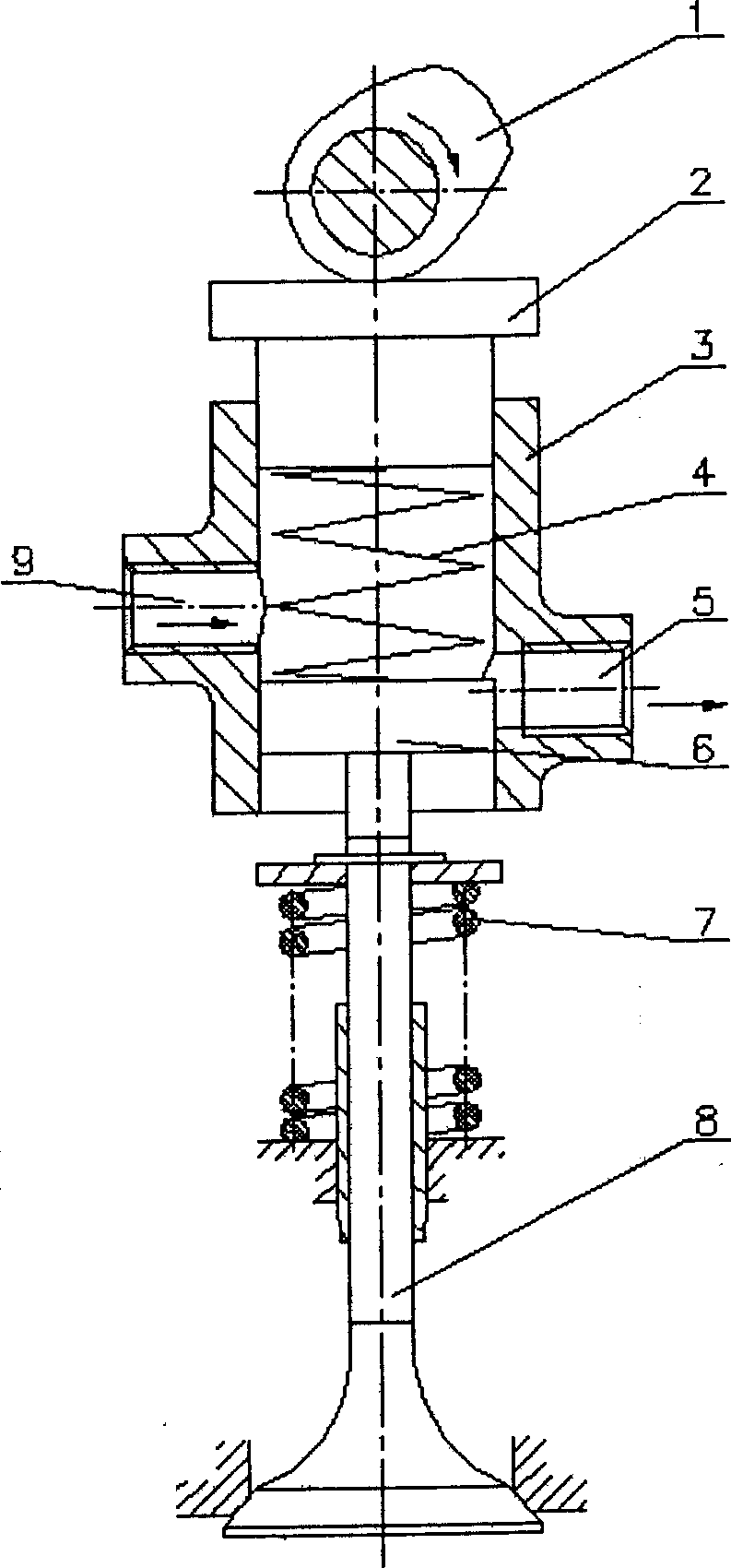
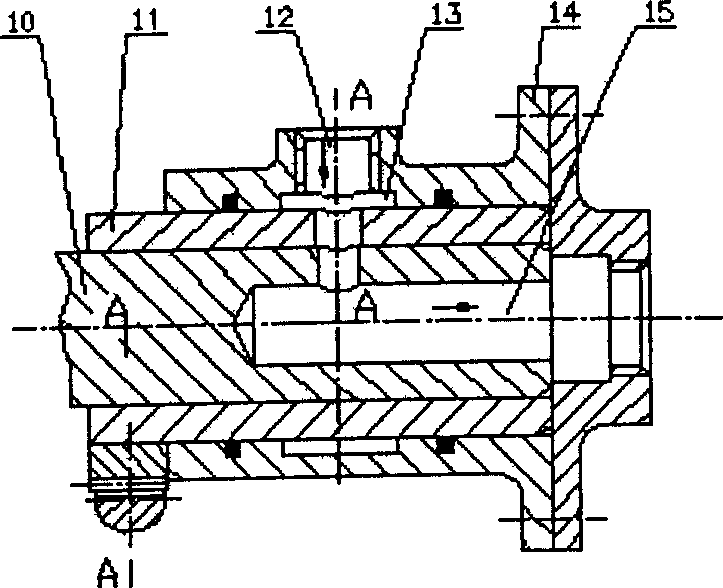
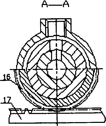
[0016] The working principle of the present invention will be described in detail below in conjunction with the accompanying drawings. exist figure 1 , figure 2 , image 3 , Figure 4 and Figure 5 Among them, the oil inlet hole 9 of the hydraulic cylinder communicates with the outlet 18 of the inlet control device through the oil pipe; the oil outlet hole 5 of the hydraulic cylinder communicates with the inlet 12 of the outlet control device through the oil pipe. Cam 1, outlet control device rotor 10 and inlet control device rotor 20 are the same shaft, and the speed is 1 / 2 of the crankshaft speed. It works as follows:

[0017] The first stage is the valve opening stage. like figure 1 As shown, at this stage, the rising section of the cam 1 drives the tappet 2, and the oil inlet hole 9 and the oil outlet hole 5 of the hydraulic cylinder are closed under the action of the hydraulic cylinder outlet control device and the hydraulic cylinder inlet control device. The tap...


PUM


Abstract

The invention relates to an air distribution device and fuel feeding system of internal-combustion engine, especially relating to the ignition internal-combustion engine. It is formed by an air gate element, a hydraulic cylinder element, a hydraulic cylinder outlet control device, a hydraulic cylinder inlet control device and a camshaft transmission element. Wherein, the open and lifting of air gate are controlled by the ascending part of cam; the reduction and close of air gate are controlled by the discharge time of liquid inside the hydraulic cylinder; the outlet control device comprises a rotor and a rotor sheath; when the rotor

Description

technical field [0001] The invention relates to a gas distribution mechanism and a fuel supply system of an internal combustion engine, in particular to a fuel supply system and a gas distribution mechanism of an ignition type internal combustion engine. technical background [0002] Ignition internal combustion engine load adjustment is achieved by changing the amount of combustible mixture entering the cylinder, that is, changing the amount of combustible mixture entering the cylinder by adjusting the throttle opening. When the speed of the internal combustion engine remains constant, the opening of the throttle valve increases, the amount of combustible mixture entering the cylinder increases, and the output power of the internal combustion engine increases accordingly; otherwise, it decreases. When the internal combustion engine works under small and medium load conditions, due to the small opening of the throttle valve, the pumping loss of the internal combustion engine...

Claims


Application Information

Patent Timeline
IPC IPC(8): F02D13/00
CPCY02T10/18Y02T10/12
Inventor 谢宗法
Owner SHANDONG UNIV
Why Eureka
Try Eureka