Automatic stereo display

An autostereoscopic and display technology, which is applied to static indicators, instruments, electrical components, etc., can solve the problems of high requirements for the action accuracy of the micro-phase difference plate driver, high requirements for the production precision of the micro-phase phase difference plate, and weakening the brightness of the display. The effect of increasing process latitude, improving clarity and increasing the content of dye molecules

Inactive Publication Date: 2006-07-19
SHANTOU GOWORLD DISPLAY +1
View PDF2 Cites 10 Cited by
  • Summary
  • Abstract
  • Description
  • Claims
  • Application Information

AI Technical Summary

Problems solved by technology

However, both the glass substrate and the plastic substrate have a certain thickness, so the reduction of the object distance is limited by using a substrate as thin as possible. In addition, setting the polarizer on the inner side of the carrier by printing will also increase production. process difficulty
[0006] In the Chinese patent CN1506714A, the structure of two micro-phase difference plates is used to realize the design of the parallax barrier that can convert 2D/3D. It does not require...

Method used


Image

  • Automatic stereo display
  • Automatic stereo display
  • Automatic stereo display

Examples


Embodiment 1

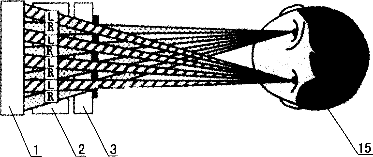
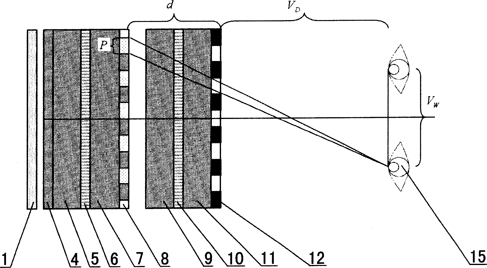
[0028] As shown in FIG. 4(a) and FIG. 5(a), this autostereoscopic display includes an image display device, and a guest-host type liquid crystal display 3 is arranged at an appropriate position in front of the image display device.

[0029] The image display device is composed of a backlight module 1 and a transmissive spatial light modulator 2 , the transmissive spatial light modulator 2 adopts a thin film transistor flat panel display, and the transmissive spatial light modulator 2 constitutes a pixel layer 2 . The transmissive spatial light modulator 2 is composed of a polarizer 4 , a substrate 5 , a liquid crystal layer 6 , a substrate 7 and a polarizer 8 .

[0030] The guest-host type liquid crystal display 3 forms a parallax barrier layer 3 . The guest-host type liquid crystal display 3 is made up of the first transparent substrate 9, the second transparent substrate 11 and the liquid crystal layer 10 doped with the dye, the liquid crystal layer 10 is arranged between th...

Embodiment 2

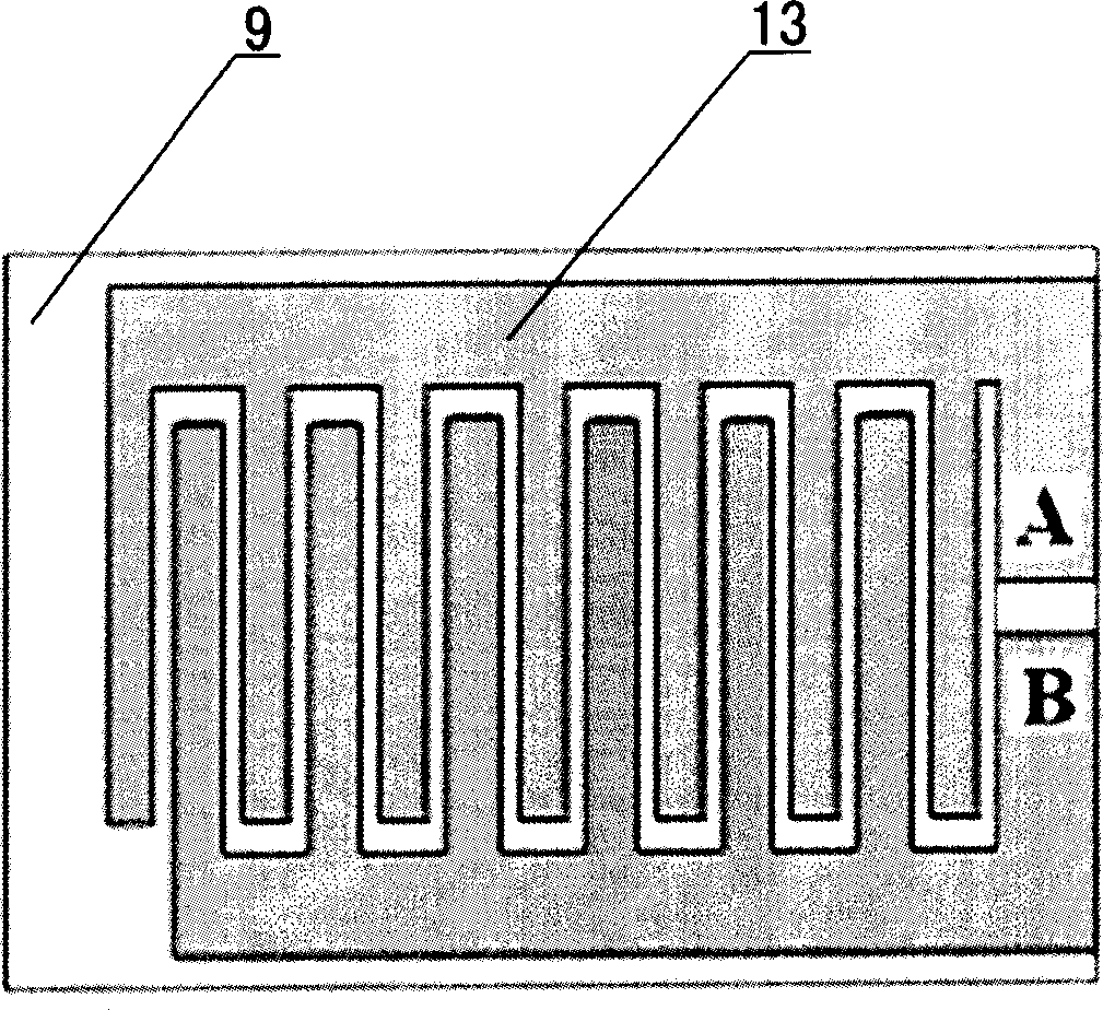
[0037] In this embodiment, the liquid crystal layer 10 adopts nematic negative liquid crystal, and the dye is black dye. You can buy a liquid crystal dye mixture that has been mixed, such as the liquid crystal doped with black dye produced by MERCK in Germany. The vertical alignment technology is adopted, and through the rubbing alignment of the transparent substrates 9 and 11 (the rubbing direction should be consistent with the polarization direction of the polarized light emitted by the image display device), the liquid crystal molecules and dye molecules are perpendicular to the first transparent substrate 9 and the second transparent substrate. The surfaces of the substrate 11 are arranged such that the arrangement direction is perpendicular to the polarization direction of the polarized light emitted by the image display device. As shown in Figure 6(a) and Figure 6(b), the electrodes 13, 14 are in the shape of stripes, and the electrodes 13 on the first transparent substr...


PUM


Abstract

The invention relates to an automatic stereoscopic display which comprises an image display. It is characterized in that it arranges a custom-host type LCD on the front of the image display.

Description

technical field [0001] The invention relates to a display, in particular to an autostereoscopic display which utilizes the parallax barrier principle to realize autostereoscopic display of images and can realize conversion between two-dimensional / three-dimensional (2D / 3D) display modes. Background technique [0002] Human vision is stereoscopic vision. When watching objects, the observer can feel the distance between the objects and the distance between the objects and the observer, that is, the sense of depth. However, due to technical constraints for a long time, most displays can only display various images through two-dimensional screens. In order to give full play to the powerful functions of human visual perception, it is an important way to develop autostereoscopic displays that can reproduce real 3D scenes. [0003] There are many methods for realizing stereoscopic display, among which the scheme of separating left and right eye images by means of a parallax barrier...

Claims


Application Information

Patent Timeline
IPC IPC(8): G02B27/22G02F1/133H01J17/49H05B33/00
Inventor 寇志起沈奕范志新吕佳鹏李永忠曾晓东
Owner SHANTOU GOWORLD DISPLAY
Why Eureka
Try Eureka