Radiator and its making method

A technology of a heat dissipation device and a manufacturing method, which is applied in the directions of cooling/ventilation/heating transformation, electrical components, electric solid devices, etc., can solve the problems such as the heat dissipation efficiency of the heat dissipation device 1 cannot be effectively improved, the flow of the working fluid is disordered, and the like

Inactive Publication Date: 2006-07-19
DELTA ELECTRONICS INC
View PDF0 Cites 10 Cited by
  • Summary
  • Abstract
  • Description
  • Claims
  • Application Information

AI Technical Summary

Problems solved by technology

This has restrictions on the design of the heat sink, and in the housing of the above-mentioned heat sink, only a space is provided to allow the working fluid to flow therein, without restricting th

Method used


Image

  • Radiator and its making method
  • Radiator and its making method
  • Radiator and its making method

Examples


Embodiment Construction

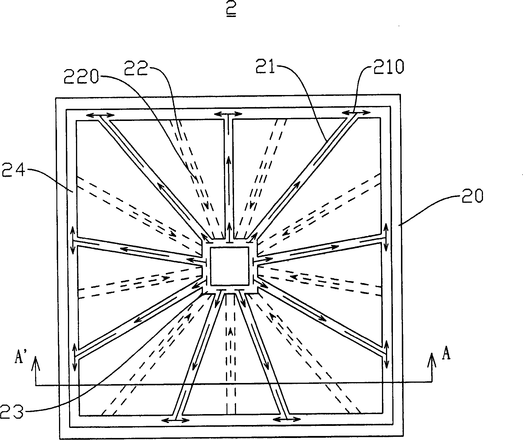
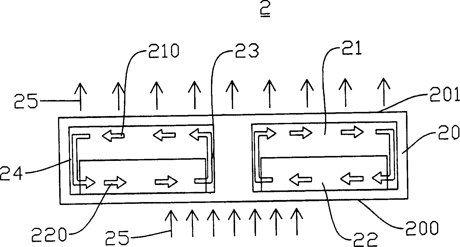
[0043] In order to clearly understand the detailed structure of the heat sink 2 in the embodiment of the present invention, refer to Figure 2A to Figure 2C . Such as Figure 2AAs shown in , the heat dissipation device 2 of the first embodiment of the present invention includes a casing 20, at least one heat dissipation channel 21, at least one return flow channel 22, a first connection channel 23 and a second connection channel 24, wherein the casing consists of Made of metal or non-metal material, it is good for dissipating heat. The heat dissipation channel 21 , the return channel 22 , the first connecting channel 23 and the second connecting channel 24 are all located in the housing 20 , and the housing 20 has working fluid inside. The first connection channel 23 connects one end of the heat dissipation channel 21 and one end of the return channel 22, and the second connection channel 24 connects the other end of the heat dissipation channel 21 and the other end of the r...


PUM


Abstract

The invention relates to a heat radiator and relative producing method, which comprises a case, a heat radiation channel for cycling the working liquid, a reflux channel, the first and second connection channels. Wherein, the heat radiation channel and the reflux channel are on different planes to avoid the turbulence when the working substance is transmitting the heat and the turbulence can reduce the heat radiation efficiency. In addition, said working substance is not needed to be transformed between liquid and gas. Therefore, the invention has wider application.

Description

technical field [0001] The invention relates to a heat dissipation device and its manufacturing method, in particular to a heat dissipation device with a channel through which working fluid can circulate to achieve heat dissipation and its manufacturing method. Background technique [0002] With the advancement of technology, the number of transistors per unit area of ​​electronic components is increasing and denser, resulting in an increase in heat generation during operation. Therefore, in order to maintain the electronic components at an effective operating temperature, most of the current methods use external fans and cooling fins to deal with the heat dissipation. Since the heat pipe can transmit a large amount of heat over a considerable distance with a small cross-sectional area and temperature difference, and can operate without an external power supply, there is no need to provide power and space utilization considerations Next, the heat pipe is one of the widely u...

Claims


Application Information

Patent Timeline
IPC IPC(8): H01L23/473H05K7/20
CPCH01L2924/0002
Inventor 蔡欣昌王宏洲陈煌坤邢泰刚
Owner DELTA ELECTRONICS INC
Why Eureka
Try Eureka