Heat radiator

A heat sink and cooling fin technology, which is applied in heat exchange equipment, electrical solid devices, semiconductor devices, etc., can solve the problems of complex processing of cooling fins, damage, and failure of heat sinks to form, etc.

Inactive Publication Date: 2012-10-31
TYNTEK
View PDF6 Cites 1 Cited by
  • Summary
  • Abstract
  • Description
  • Claims
  • Application Information

AI Technical Summary

Problems solved by technology

[0004] Although the heat dissipation module mentioned above can achieve the expected heat dissipation effect, the processing of the heat dissipation fins of this type of heat sink is complicated, requiring additional procedures and cost expenditures
Furthermore, the way of connecting and assembling the wedge grooves and wedges of adjacent heat dissipation fins is not stable in terms of stability, because each heat dissipation fin is already an extremely thin sheet, let alone the one located on the heat dissipation fin. The wedge grooves and wedges are easy to be damaged due to careless operation during the assembly process, which affects the mutual assembly function, making the heat sink unable to form

Method used


Image

  • Heat radiator
  • Heat radiator
  • Heat radiator

Examples


Embodiment Construction

[0022] Below in conjunction with accompanying drawing and embodiment the present invention is described in detail:

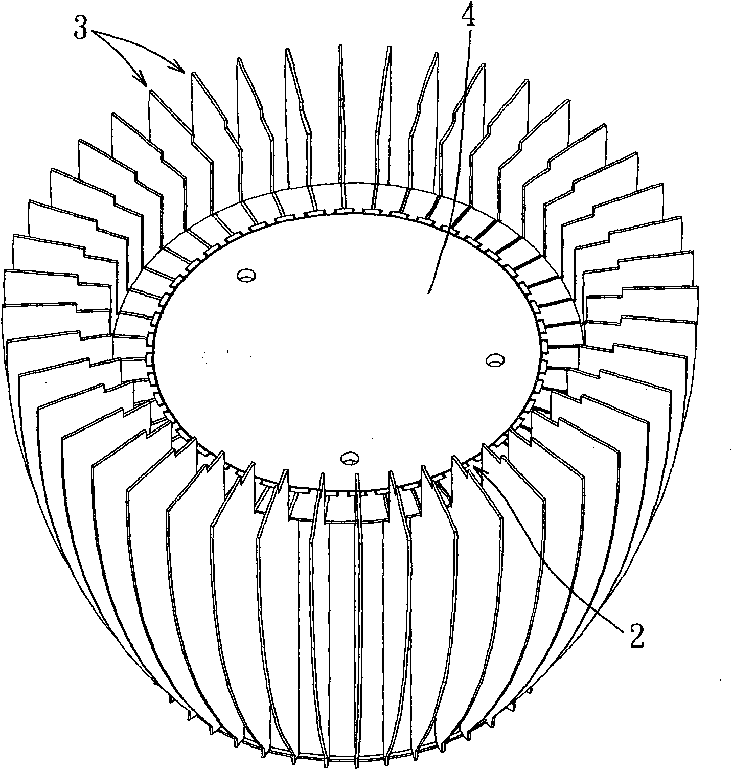
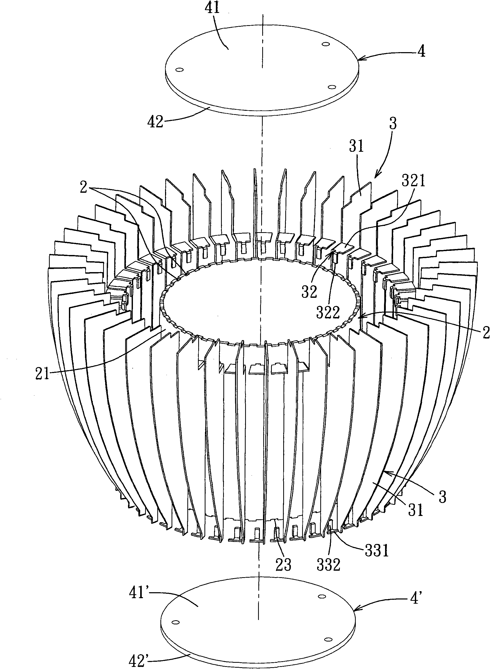
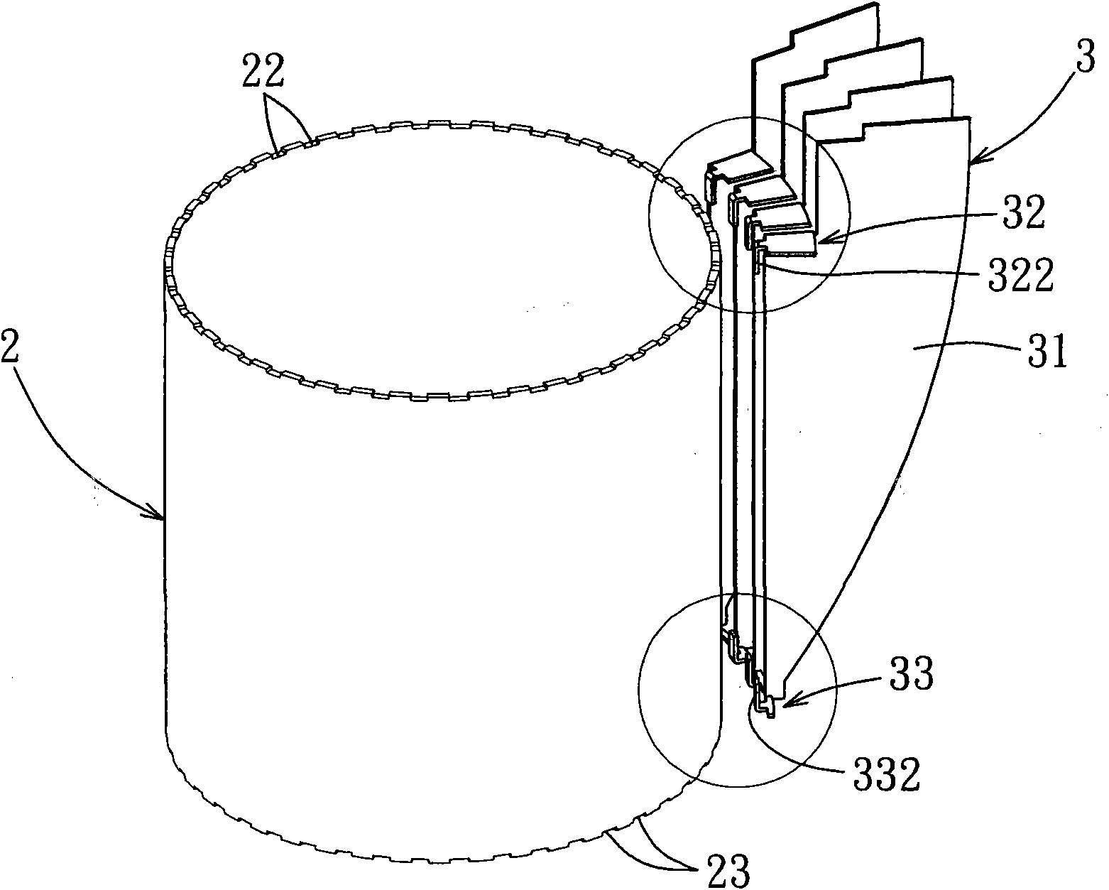
[0023] refer to Figure 1 to Figure 3 , a preferred embodiment of the radiator of the present invention includes a socket 2, a plurality of cooling fins 3, and two fixing plates 4, 4'.

[0024] The socket 2 includes a tube body 21 defining upper and lower openings 211, 212 and an inner peripheral wall 213, a first fixing portion 22 formed on the tube body 21 and adjacent to the upper opening 211, and a tube body 21 formed on the tube body 21 and The third fixing portion 23 is adjacent to the lower opening 212 . In this embodiment, the first fixing part 22 of the receiving seat 2 is a plurality of buckle grooves formed at intervals on the tube body 21 and surrounding the periphery of the upper opening 211, and the third fixing part 23 of the receiving seat 2 is formed at a plurality of intervals. The pipe body 21 surrounds the buckle groove at the periphery of ...


PUM


Abstract

The invention discloses a heat radiator which comprises a bearing base and a plurality of heat-dissipation fins. The bearing base comprises a pipe body which is defined with an upper opening and a lower opening, and a first fixing part which is formed at the pipe body and next to the upper opening. The plurality of the heat-dissipation fins surround the pipe body arranged at the bearing base, wherein each heat-dissipation fin comprises a fin body, and a second fixing part formed in the fin body and fixed at the first fixing part of the bearing base; and each of the second fixing parts is provided with a stretching section formed through stretching and bending of each fin body, and a clamping hook convexly stretching from the stretching section and buckled on the first fixing part of the bearing base. As the second fixing parts of the heat-dissipation fins are matched with the first fixing part of the bearing base, a heat-dissipation effect can be achieved after assembling.

Description

technical field [0001] The invention relates to a heat sink, in particular to a heat sink which is easy to assemble. Background technique [0002] LED has the advantages of low power, high luminous efficiency, good energy-saving effect, long service life and no pollution, so it has been widely used in daily life; it is common to install multiple LEDs in a lamp for lighting. Because LEDs will generate temperature when they work, lamps with multiple LEDs are prone to generate high heat accumulation during the lighting process. If they are not dissipated in time, LEDs will suffer from color shift, reduced brightness, and shortened service life. And problems such as immediate failure. Therefore, the heat dissipation of LEDs has always been an important issue. [0003] For example, Taiwan’s new patent No. M395787 discloses a heat dissipation module, which mainly uses the wedge grooves and wedges located under each heat dissipation fin to cooperate with each other to form a ring...

Claims


Application Information

Patent Timeline
Patent Type & Authority Applications(China)
IPC IPC(8): H01L23/367H05K7/20
CPCF28F1/20F21V29/2231F28F3/08F21V29/2212F21V29/004F21V29/773
Inventor 曾士哲徐茂松
Owner TYNTEK
Why Eureka
Try Eureka