Article storage apparatus

A storage device and article technology, applied in the directions of packaging, transportation and packaging, rigid containers, etc., can solve the problem that article storage devices cannot be stacked in high density.

Inactive Publication Date: 2006-08-02
MAKITECH
View PDF2 Cites 4 Cited by
  • Summary
  • Abstract
  • Description
  • Claims
  • Application Information

AI Technical Summary

Problems solved by technology

As a result, the problem is that item storage units cannot be packed at high densities

Method used


Image

  • Article storage apparatus
  • Article storage apparatus
  • Article storage apparatus

Examples


Embodiment Construction

[0099] The best mode for carrying out the present invention will be described below while referring to the accompanying drawings.

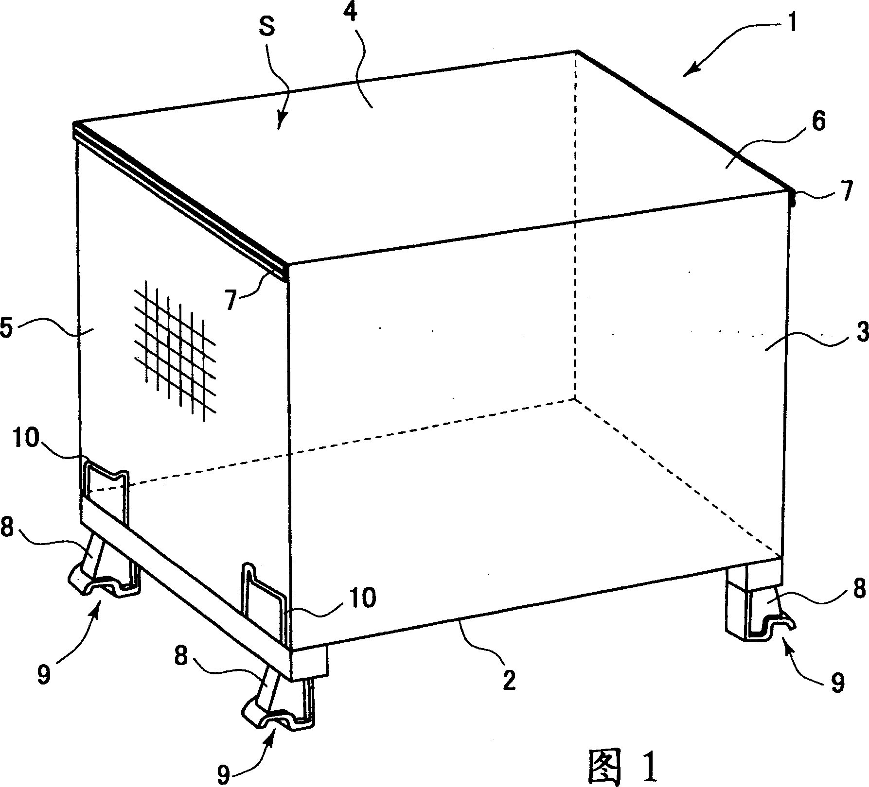
[0100] Figure 1 is a schematic perspective view of an object storage device 1 according to the invention. The article storage device 1 has a bottom lattice plate 2 (an example of a bottom plate), a front lattice plate 3 and a rear lattice plate 4 erected from the front and rear ends of the bottom lattice plate 2, and side lattices. Plates 5 and 6. In addition, an article storage space S is formed which is surrounded by each lattice-shaped plate 2-6 and opened to the upper side. In addition, the upper reinforcing member 7 is connected to the side surfaces of the side lattice panels 5 and 6 along the upper end of the panel. The reinforcing member 7 is obtained by forming using a metal plate or the like, and has a higher flexural strength than the bar-shaped members constituting each lattice-shaped plate 2-6. Further, leg portions 8 are provided i...


PUM


Abstract

The invention provides an article storage apparatus which has a high earthquake resisting strength and can achieve weight saving and cost reduction. The article storage apparatus uses a lattice-shaped panel in which a plurality of rod-like members intersect, and is provided with a bottom panel forming a loading surface for an article to be stored, front and rear lattice-shaped panels provided in a rising manner in both front and rear end portions of the bottom panel, and side lattice-shaped panels provided in a rising manner in both side portions of the bottom panel. Further, side surfaces of the side lattice-shaped panels are provided with an upper reinforcing member attached along an upper end portion of the panel and having a higher flexure strength than that of the rod-like member. Further, there are leg portions provided having engagement portions capable of engaging with at least the upper reinforcing member and provided in a lower surface of the bottom panel. The engagement portions of the leg portions of the article storage apparatuses adjacent vertically to each other are engaged with at least the upper reinforcing member, at the time of piling a plurality of the article storage apparatuses. Since the article storage apparatus is reinforced by the upper reinforcing member, it is possible to manufacture the article storage apparatus having a high earthquake resisting strength.

Description

technical field [0001] The present invention relates to an item storage device. Background technique [0002] As such an article storage device, the following Patent Documents 1 and 2 have been disclosed. This structure has a bottom plate 102, a front plate 103 arranged to rise upward from the bottom plate 102, a rear plate 104, side plates 105 and leg portions 106 provided in the lower surface of the bottom plate 102 as shown in FIG. 21A. Each plate is configured in a lattice shape within which a plurality of rod-shaped members intersect. For example, the side plate 105 is formed as Figure 21B The lattice shape is shown such that the plurality of first bar members 108 pointing in the vertical direction are orthogonal to the second plurality of bar members 109 pointing in the transverse direction and each intersection point 110 is welded. [0003] Patent Document 1 [0004] Japanese Unexamined Utility Model Publication No. 51-22941 [0005] Patent Document 2 [0006] J...

Claims


Application Information

Patent Timeline
Patent Type & Authority Applications(China)
IPC IPC(8): B65D19/12B65D19/38B65D21/032
CPCB65D2519/00502B65D2519/00611B65D2519/0096B65D2519/00512B65D19/12B65D21/0211B65D2519/00323B65D2519/00338B65D2519/00273B65D2519/00975B65D2519/00601B65D2519/00562B65D2519/0088B65D2519/00298B65D2519/00656B65D2519/00452B65D19/10
Inventor 诸永文弘
Owner MAKITECH
Why Eureka
Try Eureka