Orientation equipment

A technology for positioning devices and substrates, which is applied in the fields of electrical components, semiconductor/solid-state device manufacturing, circuits, etc. It can solve problems such as floating substrates, uneven temperature, and damaged substrates, and achieve the effect of preventing uneven temperature

Active Publication Date: 2006-08-02
TOKYO OHKA KOGYO CO LTD +1
View PDF2 Cites 6 Cited by
  • Summary
  • Abstract
  • Description
  • Claims
  • Application Information

AI Technical Summary

Problems solved by technology

[0006] In the positioning device disclosed in Patent Document 1, the air ejection port for floating the wafer is directly formed on the stage, and since the back surface of the wafer is in contact with the surface of the stage, it is easily affected by heat from the stage. The diameter of the air outlet opening on the upper surface of the stage is also small, so the air partially touches the back of the wafer, and temperature unevenness tends to occur
[0007] In the positioning device disclosed in Patent Document 2, since only the periphery of the substrate is supported, if the substrate is enlarged, the central part of the substrate cannot be supported, and warpage occurs in the central part, which may damage the substrate during alignment.
In addition, if the substrate is enlarged, it is difficult to float the substrate by the device disclosed in Patent Document 2.

Method used


Image

  • Orientation equipment
  • Orientation equipment
  • Orientation equipment

Examples


Embodiment Construction

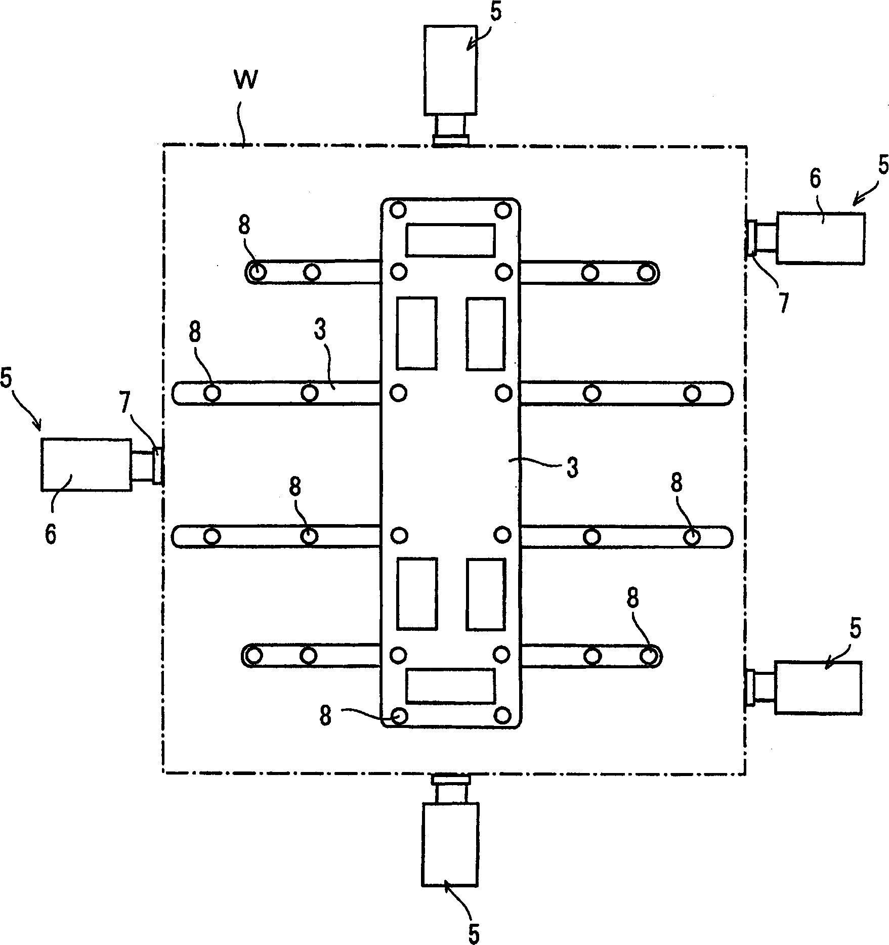
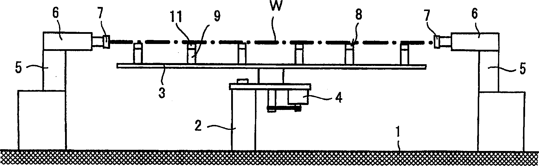
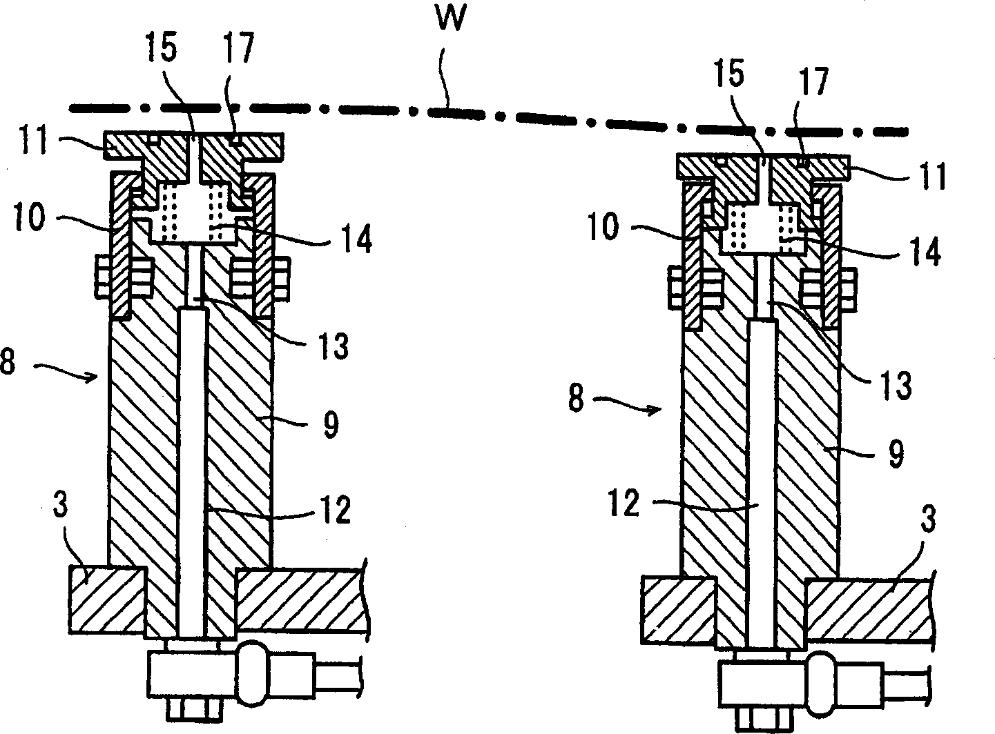
[0018] Preferred embodiments of the present invention will be described below based on the drawings. figure 1 is a top view of the positioning device in the present invention, figure 2 is a side view of the positioning device, image 3 is an enlarged cross-sectional view of the floating part.

[0019] In the positioning device, an elevating device 2 of a cylinder unit is provided on a base 1 , and a support member 3 is arranged on the elevating device 2 . This support member 3 is a combination of a plate-shaped vertical member and a rod-shaped horizontal member, and is formed in a lattice shape as a whole, and is rotatable in a horizontal plane by a motor 4 .

[0020] In addition, a plurality of alignment members 5 are provided on the base 1 so as to surround the support member 3 . The alignment part 5 has a sliding part 6 on the upper part, and the sliding part 6 moves back and forth in the horizontal direction relative to the substrate W through the operation of the pres...


PUM


Abstract

The present invention provides a positioning device which can accurately position a substrate without damaging it even if the substrate is made large. In a state where a slide member 6 is retreated, a cylinder unit 2 is operated to raise a supporting member 3, and a substrate W is received by the upper surface of the reception part 11 of a lifting member 8. Next, the cylinder unit 2 is operated to lower the supporting member 3 until the substrate W is on the same level of the slide member 6 of an alignment member 5, and a valve is changed over to connect the piping 12 of the lifting member 8 to a compressed air source. An air is allowed to be jetted from grooves 16 and 17 on the upper surface of the reception part 11 of the lifting member 8, so as to lift the substrate W from the upper surface of the reception part 11, move forward the slide member 6 of the alignment member 5, and bring a pusher 7 into contact with the edge of the substrate W for positioning.

Description

technical field [0001] The present invention relates to a positioning device suitable for a standby unit or the like arranged in front of a substrate processing apparatus. Background technique [0002] Devices disclosed in Patent Document 1 and Patent Document 2 are known as devices for positioning substrates such as semiconductor wafers and glass substrates in a floating state. [0003] In the device disclosed in Patent Document 1, air is jetted from an air jet opening opened on the stage to float the wafer, and in this state, the wafer is pushed by the air from the air nozzle disposed on one side. Positioning is performed on the reference member provided at the place opposite to the air nozzle. In the device disclosed in Patent Document 2, a suction pad is provided at the corner or the periphery of the frame-shaped workbench, the suction pad is added with an air ejection function, and the photomask (substrate) is blown by the air ejected from the suction pad. ) to float ...

Claims


Application Information

Patent Timeline
Patent Type & Authority Applications(China)
IPC IPC(8): H01L21/68
CPCH01L21/67017H01L21/68
Inventor 谷本恒夫楫间淳生高濑真治山口和伸
Owner TOKYO OHKA KOGYO CO LTD
Why Eureka
Try Eureka