One-way delay measuring method

A measurement method, one-way delay technology, applied in error detection/prevention using signal quality detectors, digital transmission systems, electrical components, etc., can solve delay differences, one-way delay errors, and cannot guarantee one-way delay measurement accuracy and other issues to achieve the effect of maintaining low cost and low complexity

Inactive Publication Date: 2006-08-02
HUAWEI TECH CO LTD
View PDF0 Cites 24 Cited by
  • Summary
  • Abstract
  • Description
  • Claims
  • Application Information

AI Technical Summary

Problems solved by technology

The basis for calculating the one-way delay is that the packets travel the same path and have the same bandwidth. However, in fact, the two directions of the packet may take different paths, or even different transmission media, or two directions. Different bandwidth and congestion levels will lead to different delays in the two directions, so the calculated one-way delay has a large error
It can be seen that although the problem of time synchronization is avoided by measuring the round-trip delay, the accuracy of the one-way delay measurement cannot be guaranteed

Method used


Image

  • One-way delay measuring method
  • One-way delay measuring method
  • One-way delay measuring method

Examples


Embodiment approach 2

[0040] According to the idea above, the present invention can also be implemented in the second embodiment below, including:

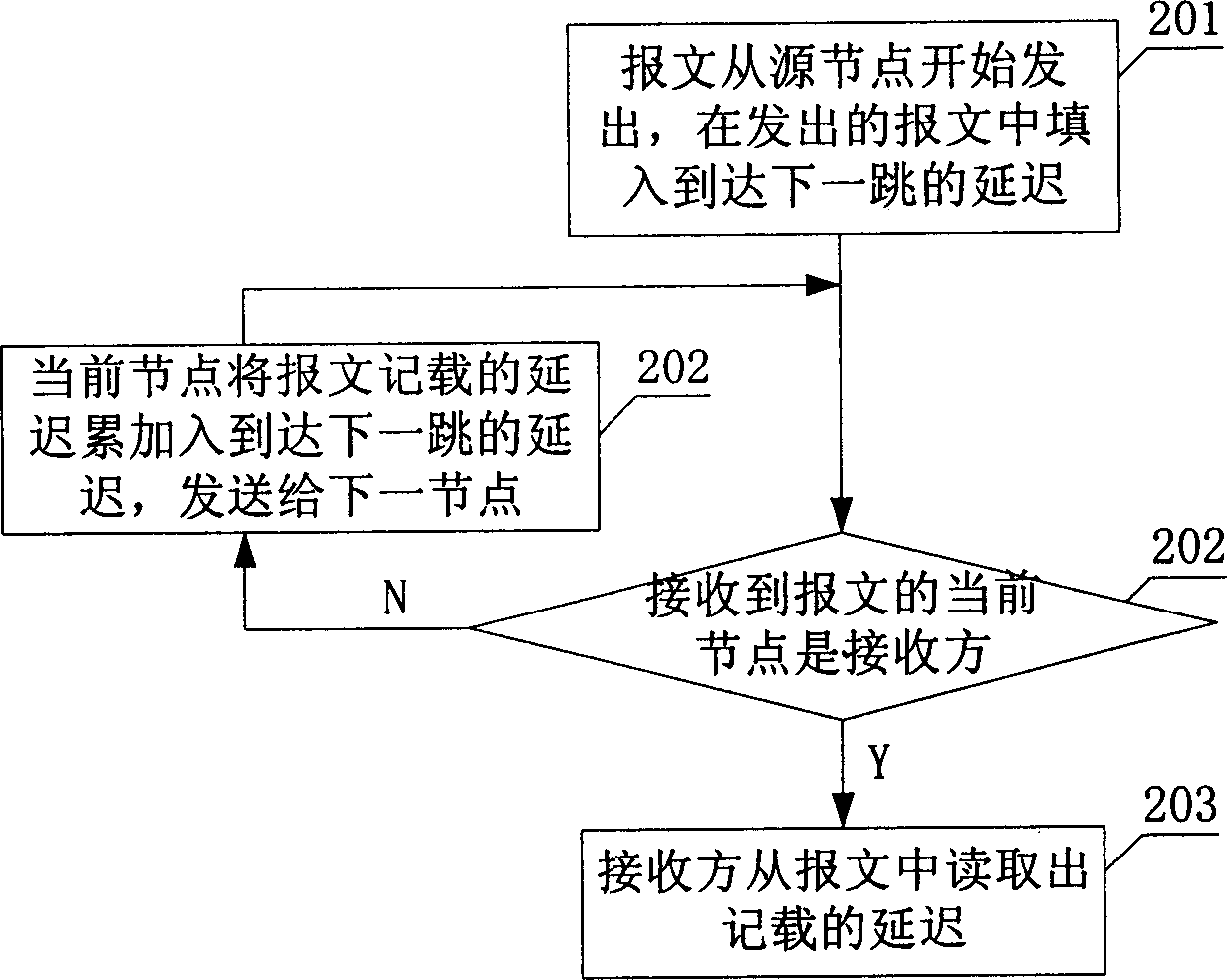
[0041] The first step: the message is sent from the source node, and the node ID and the delay D to reach the next hop are filled in the message 2 = L 1 / r 1 +p 1 .

[0042] Second step: the next node j refers to the method in step 202 to obtain the delay (T j -R j )+L j / r j +p j , record in the message, and add the ID of node j; then send it to the next node. The execution steps of the next node are the same as this step.

[0043] Step 3: When the message arrives at the receiver, each node ID and corresponding delay can be read from the message to obtain the delay distribution, and the sum of all delay records can be calculated to obtain the one-way delay.

[0044] Based on the above two embodiments, the two embodiments can be combined to further obtain the following embodiment three, which is briefly described:

[0045] The first step: ...


PUM


Abstract

This invention provides a kind of measuring method for unidirectional delay, which is message transmission delay from transmitting part to receiving part. It concludes: A) transmitting part keeps the delay to the neighboring next node in the current message and transmits it to the neighboring next node; B) the node, which receives the said message, is used as current transmitting part. Step A is repeated until current node is receiving part; C) receiving part abstracts each delay kept in the message and calculates total delay. Or when transmitting message to next node every time, the kept delays are accumulated. This invention does not need time synchronism between network node facilities to achieve precise unidirectional delay measuring.

Description

technical field [0001] The invention relates to the technical field of signal transmission measurement, in particular to a method for measuring one-way delay. Background technique [0002] In signal transmission, the basic indicators of service quality (QoS) are: bandwidth, loss rate, delay, jitter (that is, delay variation). The purpose of QoS is to control the bandwidth, loss rate, delay and jitter of the agreed service within the agreed range in the case of network congestion. Services such as real-time voice, video, and VPN generally have QoS requirements. [0003] Among them, the loss of transmitted packets is mainly caused by equipment or link failure, line error, or buffer queue overflow, and buffer queue overflow is the most common. Latency is one of the indicators of QoS. When the egress bandwidth is much larger than the ingress bandwidth, the packets will not be queued in the buffer queue, but will be forwarded quickly with the minimum delay. The packets will not...

Claims


Application Information

Patent Timeline
Patent Type & Authority Applications(China)
IPC IPC(8): H04L12/26H04L1/20
Inventor 陈耀明杨洋
Owner HUAWEI TECH CO LTD
Why Eureka
Try Eureka